



عرض 5 من كل النتائج




Filter by price
Filter by brands



NI C Series Analog Input Modules
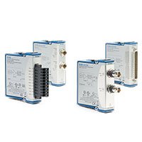
NI C Series Analog Input Modules provide modular measurement interfaces for voltage, current, temperature, strain, vibration, bridge sensors and other real-world signals. They install in compatible CompactDAQ and CompactRIO systems, allowing engineers to combine signal conditioning, analog conversion and sensor connectivity in a compact measurement platform.
The correct module is selected from the sensor’s electrical output, not only the physical parameter being measured. A pressure sensor, for example, can require a voltage, current, bridge, charge or IEPE-compatible input depending on its construction and signal conditioner.
What Is a C Series Analog Input Module?
A C Series analog input module converts external analog signals into digital data for a CompactDAQ or CompactRIO system. Many modules include application-specific functions such as thermocouple cold-junction compensation, RTD excitation, bridge completion, IEPE power, input isolation, anti-alias filtering or current measurement.
Using a dedicated signal-conditioning module can improve accuracy, noise performance and sensor compatibility compared with connecting a low-level sensor directly to a general-purpose voltage input.
The measured physical quantity does not uniquely identify the required module. Always obtain the sensor datasheet and confirm its electrical output, maximum signal level, excitation requirement, wiring method, source impedance, grounding arrangement and required bandwidth.
C Series Analog Input Module Types
Input Type
Typical Signal
Integrated Functions to Consider
Typical Applications
General-Purpose Voltage Input
Conditioned analog voltage from sensors, transducers or external signal conditioners
Input range, resolution, sample rate, isolation, differential or single-ended connection
Laboratory measurement, process signals, electronics testing and general DAQ
Current Input
Current-loop or industrial current signals, including 4–20 mA systems
Current range, shunt architecture, isolation, loop-power arrangement and field wiring
Industrial process monitoring, transmitters and distributed sensor systems
Thermocouple Input
Low-level thermocouple voltage
Cold-junction compensation, thermocouple type, open-sensor detection and terminal design
Thermal testing, process temperature monitoring and environmental chambers
RTD and Resistance Input
Resistance temperature detector or resistive sensor output
Excitation current, 2-, 3- or 4-wire connection and lead-resistance compensation
Precision temperature measurement and long-duration thermal logging
Bridge and Strain Input
mV/V bridge output from strain gauges, load cells, pressure sensors or torque transducers
Bridge completion, excitation, shunt calibration, remote sensing and bridge configuration
Structural testing, force, load, pressure, torque and material characterization
Dynamic Signal Input
IEPE, piezoelectric, acoustic or vibration signals
IEPE excitation, coupling, anti-alias filtering, simultaneous sampling and dynamic range
Vibration, acoustics, rotating machinery and condition monitoring
Universal Analog Input
Mixed low-speed voltage, current, thermocouple, RTD and resistance measurements
Supported measurement modes, channel flexibility, input range and scan rate
Mixed sensor systems, laboratory development and flexible validation setups
Representative NI C Series Analog Input Modules
Model
Unique Category
Key Differentiator
Best Fit
NI-9205
General-Purpose Voltage Input
Multichannel analog voltage measurement for general data acquisition
Conditioned sensor outputs, laboratory signals and mixed analog measurement systems
NI-9208
Current Input
Current measurement interface for industrial and transmitter signals
4–20 mA monitoring, process instrumentation and current-output sensors
NI-9213
Thermocouple Input
High-channel-count thermocouple measurement architecture
Thermal mapping, environmental chambers and multichannel temperature logging
NI-9217
RTD Input
Resistance-based temperature measurement with RTD wiring support
Precision thermal measurement with 2-, 3- or 4-wire RTDs
NI-9219
Universal Analog Input
Flexible support for several low-speed analog and sensor measurement modes
Mixed-sensor systems, prototyping and applications with changing input requirements
NI-9234
Dynamic Signal Input
Simultaneous dynamic acquisition with IEPE sensor support
Vibration, acoustic, IEPE accelerometer and microphone measurements
NI-9237
Bridge and Strain Input
Bridge-based sensor measurement with dedicated strain and transducer conditioning
Strain gauges, load cells, force, pressure and torque transducers
This table represents the principal C Series analog input architectures rather than every available model. Verify exact part number, hardware revision, terminal accessory and software support before ordering.
How to Choose a C Series Analog Input Module
1. Identify the Electrical Output
Begin with the sensor or device datasheet. Determine whether the output is voltage, current, thermocouple voltage, RTD resistance, bridge mV/V, IEPE, charge or another signal type. Sensors that measure the same physical property can require very different analog input hardware.
Record the nominal output, maximum output, source impedance, excitation requirement, connector type, grounding arrangement and sensor sensitivity. This information defines the correct module architecture and input range.
2. Match Signal Conditioning and Excitation
Low-level sensors often need more than an analog-to-digital converter. Thermocouples require cold-junction compensation, RTDs require stable excitation and lead-resistance compensation, bridge sensors require excitation and completion, and IEPE sensors require compatible constant-current power.
Confirm whether the required conditioning is integrated into the module, supplied by a terminal block or provided through an external sensor conditioner. Do not connect externally powered sensors to module excitation terminals until voltage limits and wiring have been verified.
3. Select the Correct Input Range
Choose the smallest range that safely accommodates the maximum expected signal, including offset, overload conditions and common-mode voltage. This normally improves effective resolution, but the selected range must allow for startup transients, sensor tolerance and abnormal conditions.
For bridge sensors, compare the sensor’s rated output in mV/V with the module’s supported bridge ranges. For conditioned voltage outputs, include the output offset and maximum possible field signal rather than only the nominal value.
4. Determine Sample Rate and Bandwidth
Select the measurement bandwidth first, then confirm that the module sample rate, filtering and chassis architecture support it. Temperature and process monitoring may need only a few samples per second, while acoustic, vibration, impact and rotating-machinery measurements can require much higher rates.
Maximum sample rate is not identical to usable measurement bandwidth. Delta-sigma modules often include digital filtering that improves noise and alias rejection but can introduce group delay. Account for that delay in control, triggering and correlation applications.
5. Evaluate Simultaneous Sampling
Simultaneous sampling is important when phase relationships must be preserved between channels, such as vibration, strain, force, pressure, power and acoustic measurements. Multiplexed architectures can be suitable for slower signals but do not acquire all channels at exactly the same instant.
For mixed-module systems, verify how clocks, triggers and timestamps are shared by the selected CompactDAQ or CompactRIO platform.
6. Review Isolation and Grounding
Isolation helps manage common-mode voltage, ground-potential differences and noise in distributed systems. However, isolation topology varies by module. Channel-to-channel isolation, bank isolation and non-isolated inputs have different implications for sensor wiring and grounding.
Long cable runs, grounded machinery, externally powered transmitters and multiple earth references should be reviewed for ground-loop risk before the hardware is installed.
Temperature Measurement Considerations
Thermocouples
Thermocouples generate a small voltage representing the temperature difference between the measurement junction and reference junction. Accurate measurement requires support for the required thermocouple type and cold-junction compensation at the point where thermocouple wire transitions to copper terminals.
Extension-wire type, terminal-block design, connector material and local thermal gradients can materially affect measurement accuracy. Open-thermocouple detection should be checked when working with sensitive low-level signals.
RTDs
RTDs require excitation and lead-resistance compensation. Two-wire measurements include lead resistance, three-wire connections compensate when conductor resistances are closely matched, and four-wire configurations provide the best lead-resistance cancellation.
Consider sensor self-heating, cable resistance, excitation current and the required uncertainty when configuring an RTD measurement system.
Bridge, Force and Strain Measurement Considerations
Bridge-based transducers are commonly used for strain, force, load, torque and pressure. They produce a differential output proportional to excitation voltage and are often specified in mV/V.
Quarter bridge: Uses one active strain element and generally requires compatible bridge completion.
Half bridge: Uses two active elements or an appropriate completion arrangement.
Full bridge: Uses four active elements and commonly provides higher sensitivity and improved temperature compensation.
Check bridge resistance, rated output, excitation limit, cable length, remote sense, shunt-calibration requirements and the expected measurement bandwidth. A general voltage module is not a substitute for a dedicated bridge module when sensor excitation and ratiometric measurement are required.
Dynamic Signal Measurement Considerations
Dynamic measurements require low-noise inputs, suitable frequency response, sufficient dynamic range and appropriate anti-alias filtering. IEPE accelerometers and microphones require compatible constant-current excitation. Charge-mode piezoelectric sensors require charge-capable conditioning or an external charge amplifier.
Confirm the sensor output type, frequency range, coupling mode, IEPE current requirement, sample rate, phase relationship and connector type. A high sample rate cannot correct inadequate dynamic range or incorrect sensor conditioning.
CompactDAQ and CompactRIO Compatibility
C Series analog input modules can be used in compatible CompactDAQ systems and CompactRIO systems. Compatibility depends on the exact chassis or controller, module model, sample mode, software version and required synchronization behavior.
CompactDAQ systems are generally selected for modular sensor acquisition and data logging. CompactRIO is appropriate when the application requires embedded real-time processing, user-programmable FPGA logic or deterministic control in addition to analog measurement.
Software and Accessories
NI-DAQmx is commonly used with CompactDAQ systems for device discovery, channel configuration, timing, scaling and data acquisition. CompactRIO systems can require NI-RIO, LabVIEW Real-Time, LabVIEW FPGA or other software depending on the controller and application architecture.
Terminal blocks, connector blocks and sensor cables should be treated as part of the measurement system. They can provide cold-junction sensors, bridge-completion resistors, attenuation, shielding or sensor-specific connections that a generic cable does not provide.
Typical Applications
Temperature, pressure, strain, force and torque measurement
Automotive, aerospace and structural validation
Machine condition monitoring and vibration analysis
Industrial process and 4–20 mA transmitter monitoring
Battery, power-electronics and energy-system testing
Environmental and long-duration data logging
Acoustic, microphone and IEPE accelerometer measurement
Laboratory research and engineering development
Automated sensor validation and production test
Embedded real-time control and hardware-in-the-loop systems
C Series Analog Input Module Procurement Guide
Provide the following information for accurate module selection and quotation:
Sensor manufacturer and complete sensor model
Measured parameter and expected measurement range
Electrical output type, nominal sensitivity and maximum signal
Required excitation voltage, current or frequency
Required channel count and future expansion needs
Required sample rate, bandwidth and test duration
Accuracy, resolution and synchronization requirements
Isolation, grounding and common-mode conditions
Existing CompactDAQ chassis or CompactRIO controller model
Required terminal blocks, cables and connector accessories
Operating system, driver and software version
New or pre-owned hardware preference
FAQ
Can a general voltage input module measure any sensor?
Only when the sensor already provides a compatible conditioned voltage output. Sensors requiring cold-junction compensation, RTD excitation, bridge completion, IEPE power or charge conditioning normally require a dedicated module or external signal conditioner.
What is the difference between a thermocouple module and an RTD module?
A thermocouple module measures low-level thermocouple voltage and uses cold-junction compensation. An RTD module measures resistance using excitation and lead-resistance compensation. They are not interchangeable even though both measure temperature.
Is simultaneous sampling necessary for temperature measurement?
Usually not, because temperature changes relatively slowly. Simultaneous sampling is more important for vibration, strain, force, power, impact and other dynamic applications where phase relationships must be preserved.
Can an IEPE module measure a charge-mode piezoelectric sensor?
Not automatically. IEPE sensors require constant-current excitation, while charge-mode piezoelectric sensors require charge-capable conditioning or an external charge amplifier. Confirm the sensor output before connection.
Why is the terminal block important?
The terminal block can provide cold-junction compensation, bridge completion, sensor excitation routing, shunt calibration or suitable shield connections. The wrong accessory can reduce accuracy or prevent the required measurement configuration.
Can C Series analog input modules be used with CompactRIO?
Yes, when the module is supported by the selected CompactRIO chassis or controller and software architecture. Confirm the exact controller, FPGA target, module support and required timing behavior before installation.
Related NI C Series Solutions
Explore the complete NI C Series module range for digital, communication, FPGA adapter and high-speed acquisition interfaces. Pair analog input modules with a compatible CompactDAQ chassis, CompactDAQ controller or CompactRIO platform according to the required deployment and processing architecture.
NI C Series Analog Input Modules from PXISOURCE
PXISOURCE supports engineers, system integrators and procurement teams with sensor-interface identification, C Series module selection, CompactDAQ and CompactRIO compatibility review, terminal-block matching and legacy-module replacement. Send the sensor datasheet, required channel count, sample rate, existing platform model and preferred hardware condition for a technically matched quotation.
Need help selecting an NI C Series analog input module? Email [email protected] or contact PXISOURCE on WhatsApp.