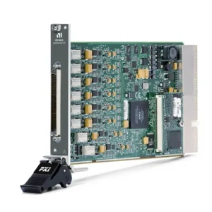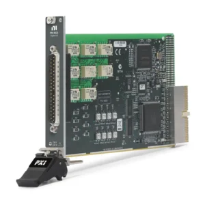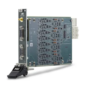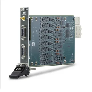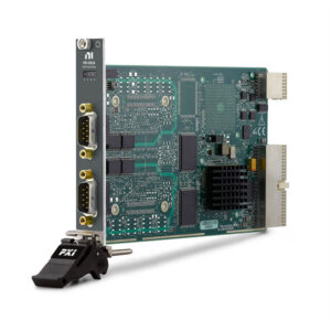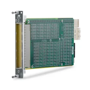


PXI-2545 2.7 GHz Terminated RF Multiplexer
The NI PXI-2545 is a terminated 4×1 PXI RF multiplexer switch module designed for automated routing of 50 Ω signals from DC to 2.7 GHz. It connects one of four channel ports to a common RF port while routing inactive channels to internal 50 Ω terminations.
The terminated architecture helps prevent high-power reflections caused by open channels and provides a defined impedance for inactive RF paths. The module is suitable for receiver testing, source selection, communications validation and automated RF production systems.
Key Features of the PXI-2545
- Terminated 4×1 RF multiplexer topology
- DC to 2.7 GHz frequency range
- 50 Ω nominal characteristic impedance
- Four channel ports and one common port
- Five gold-plated SMA jacks
- 30 V maximum switching voltage
- 0.5 A switching and carry current
- 10 W channel-to-common RF power
- 1.5 W internal termination rating at 25°C
- Less than 2 dB insertion loss to 2.7 GHz
- Latching electromechanical relays
- Onboard relay-count tracking
- PXI trigger and NI-SWITCH support
PXI-2545 Technical Specifications
| Product Model | PXI-2545 |
|---|---|
| Part Number | 778572-45 |
| Product Type | Terminated PXI RF Multiplexer |
| Topology | Terminated 4×1 multiplexer |
| Frequency Range | DC to 2.7 GHz |
| Characteristic Impedance | 50 Ω nominal |
| Maximum Switching Voltage | 30 V |
| Maximum Switching Current | 0.5 A per channel |
| Maximum Carry Current | 0.5 A per channel |
| Maximum Channel-to-Common RF Power | 10 W |
| Termination Power at 25°C | 1.5 W |
| Insertion Loss to 1 GHz | Less than 1 dB |
| Insertion Loss to 2.7 GHz | Less than 2 dB |
| Typical Isolation to 1 GHz | Greater than 60 dB |
| Typical Isolation to 2.7 GHz | Greater than 45 dB |
| Typical Propagation Delay | 1.3 ns |
| Typical Rise Time | 93 ps |
| Maximum Relay Operate Time | 10.4 ms |
| Listed Scan Rate | 45 cycles/s |
| Relay Type | Electromechanical, latching |
| I/O Connectors | Five gold-plated SMA jacks |
| Bus Connection | PXI hybrid |
| Module Format | 3U, one-slot PXI/cPCI module |
Terminated 4×1 Topology
One channel is connected to the common RF port while the inactive channels are connected to internal 50 Ω terminations. This provides a defined load to inactive sources and reduces reflections compared with an open, unterminated path.
The internal terminations cannot dissipate the full 10 W channel-to-common power. Each termination is rated for 1.5 W at 25°C and must be derated when ambient temperature rises above 25°C.
2.7 GHz RF Performance
The PXI-2545 is specified for signals through 2.7 GHz. Insertion loss is less than 1 dB to 1 GHz and less than 2 dB to 2.7 GHz.
Typical isolation is greater than 60 dB through 1 GHz and greater than 45 dB through 2.7 GHz. Complete system performance also depends on cables, adapters, fixtures and connector condition.
10 W RF Signal Path
The selected channel-to-common path supports up to 10 W within the simultaneous voltage and current ratings. The internal termination power limit is much lower and must be considered separately.
NI recommends against switching active RF signals. During relay actuation, a channel can be momentarily unterminated and expose the source to reflected power.
Latching Electromechanical Relays
Latching relays retain their selected state without continuous coil power. This reduces steady-state power consumption and heat compared with continuously energized relay coils.
Electrical relay life depends on switched power, signal type and switching frequency. Relay-count information can help identify channels approaching their expected service life.
Typical PXI-2545 Applications
- RF receiver input selection
- Multiple RF source routing
- Communications equipment testing
- Antenna-path selection
- RF component characterization
- Multi-DUT production testing
- Automated spectrum-analyzer routing
- Signal-generator output distribution
NI-SWITCH Software Support
The PXI-2545 is controlled through NI-SWITCH. Software can select channels, disconnect all routes, create scan lists, configure PXI triggers and retrieve relay-count information.
NI Switch Executive can define meaningful route names when the PXI-2545 is part of a larger RF switching system.
SMA Cable Selection
Use 50 Ω SMA cables and adapters rated above the highest operating frequency and RF power. Cable insertion loss and return loss should be included in the test-system calibration.
Avoid repeated overtightening or bending close to the connector because damaged SMA interfaces can increase insertion loss and VSWR.
PXI-2545 Troubleshooting
The common port receives no signal
Verify that the correct channel is selected and inspect both SMA cables. Confirm that the signal source is connected to the intended channel rather than an inactive terminated path.
The source output power drops
Check whether the source is connected to an internal termination and whether termination power has been exceeded. Confirm the programmed switch state before enabling high RF power.
The module becomes unusually warm
Review internal termination power and ambient-temperature derating. Reduce RF power and allow the module to cool before continuing.
Insertion loss is higher than specified
Inspect and clean SMA connectors, replace questionable cables and verify that the measurement reference plane excludes external cable loss where appropriate.
The relay does not change state
Confirm NI-SWITCH communication and inspect the relay count. Test the route without applied RF power and determine whether the problem is inside the module or in the external path.
PXI-2545 vs PXI-2594
| Feature | PXI-2545 | PXI-2594 |
|---|---|---|
| Topology | Terminated 4×1 | Unterminated 4×1 |
| Maximum Frequency | 2.7 GHz | 2.5 GHz |
| Internal Terminations | Yes | No |
| Maximum RF Path Power | 10 W | 10 W |
| Best Suited For | Applications requiring inactive-path termination | Lower-loss unterminated routing |
Recommended Related Products
- PXI-2594 2.5 GHz RF Multiplexer
- PXI-2595 5 GHz RF Multiplexer
- PXI-2546 RF Multiplexer
- PXI-2547 RF Multiplexer
- PXIe-2593 Configurable RF Multiplexer
Frequently Asked Questions
What is the PXI-2545 part number?
The standard NI ordering part number is 778572-45.
What is the topology?
The PXI-2545 is a terminated 4×1 RF multiplexer.
What is the maximum frequency?
The module is specified for RF signals from DC to 2.7 GHz.
What is the internal termination rating?
Each internal termination is rated for 1.5 W at 25°C and must be derated at higher temperatures.
Can 10 W be applied to an internal termination?
No. The 10 W rating applies to the selected channel-to-common path, not the internal termination.
Does it use latching relays?
Yes. The PXI-2545 uses latching electromechanical relays.
Which connectors are used?
The module provides five gold-plated female SMA jacks.
Request a Quote for the PXI-2545
Contact us for current availability and project pricing for the PXI-2545 2.7 GHz Terminated RF Multiplexer. We can also help select compatible SMA cables and alternative RF switch modules.