




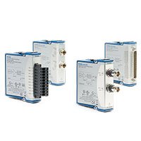


C系列 模拟量输出模块
NI C Series Analog Output Modules
NI C Series Analog Output Modules generate controlled voltage or current signals from compatible CompactDAQ and CompactRIO systems. They are used to provide analog setpoints, actuator commands, control references, simulated sensor signals, waveform stimulus and industrial current-loop outputs.
The correct C Series analog output module depends on the electrical input required by the receiving device. Select voltage-output hardware for voltage-controlled equipment and current-output hardware for current-loop devices. Confirm range, update rate, load, isolation, output timing and fault-state behavior before connection.
What Is a C Series Analog Output Module?
A C Series analog output module converts digital values from the CompactDAQ or CompactRIO platform into controlled analog voltage or current signals. The module can generate static setpoints, timed updates or buffered waveforms, depending on its architecture and the selected chassis or controller.
Analog output modules are commonly used for valve commands, inverter references, programmable test stimulus, actuator control, sensor simulation, process control, analog instrumentation and hardware-in-the-loop systems.
An analog output module is not automatically a power supply, electronic load or source measure unit. Its output range, current-drive capability, compliance voltage and load requirements must match the receiving device. Do not use a general analog output to drive a load that requires more voltage, current or power than the module can safely provide.
C Series Analog Output Module Types
Output Type
Typical Signal
Primary Selection Factors
Typical Applications
General-Purpose Voltage Output
Bipolar or unipolar analog voltage
Voltage range, resolution, channel count, update rate, output impedance and load drive
Analog setpoints, sensor simulation, test stimulus and actuator references
High-Speed Voltage Output
Buffered or continuously updated voltage waveform
Sample rate, waveform memory, update timing, synchronization and settling behavior
Dynamic control, waveform generation and hardware-in-the-loop testing
High-Density Voltage Output
Multiple analog voltage channels
Channel count, per-channel range, aggregate update rate and wiring density
Large control systems, channel simulation and multiaxis setpoint generation
Current Output
Industrial current-loop output, including 0–20 mA or 4–20 mA operation where supported
Current range, compliance voltage, external supply, isolation and loop wiring
Process control, PLC interfaces, transmitters and industrial setpoint control
Isolated Analog Output
Voltage or current output with electrical isolation
Isolation topology, common-mode conditions, grounding and field-wiring requirements
Distributed machinery, industrial cabinets and systems with ground-potential differences
Representative NI C Series Analog Output Modules
Model
Unique Category
Key Differentiator
Best Fit
NI-9262
High-Speed Voltage Output
Timed analog voltage generation for dynamic output applications
Waveform stimulus, dynamic references and synchronized control systems
NI-9263
General-Purpose Voltage Output
Multichannel analog voltage output for common control and simulation tasks
Analog setpoints, test fixtures, actuator references and sensor simulation
NI-9264
High-Density Voltage Output
Higher channel density for multichannel analog voltage control
Large control systems, simulation racks and multichannel validation
NI-9265
Current Output
Analog current output for industrial and process applications
Current-loop control, process interfaces and transmitter simulation
NI-9269
High-Speed Voltage Output
High-update-rate analog voltage output architecture
Dynamic stimulus, rapid setpoint updates and synchronized analog output
NI-9273
High-Density Current Output
Multichannel current output for industrial control applications
Multiple current loops, actuator commands and distributed process systems
This table represents common analog output architectures rather than every C Series output model. Confirm the exact module, hardware revision, required terminal accessory and supported software before ordering.
How to Choose a C Series Analog Output Module
1. Identify the Receiving Device Input
Start with the datasheet for the device being controlled. Determine whether it accepts voltage, current, a current loop, a differential signal or another control interface. Record its allowed range, input impedance, common-mode limits, grounding arrangement and required update behavior.
Do not select an output module solely because it has the same nominal range as the receiving device. The output architecture, load requirement and fault behavior must also be compatible.
2. Choose Voltage or Current Output
Voltage output modules are commonly used for analog command signals, programmable references, sensor simulation and test stimulus. Current output modules are commonly selected for industrial equipment, long cable runs and control interfaces designed around current loops.
For current output, confirm the required loop range, external loop-power arrangement, compliance voltage and maximum load resistance. A current source cannot maintain the commanded current if the connected load requires more compliance voltage than the output can provide.
3. Determine Static or Dynamic Output Requirements
Static outputs are suitable for slowly changing commands such as a valve reference, voltage bias or process setpoint. Dynamic outputs are required when the system must generate continuous waveforms, rapid transitions or synchronized sample-by-sample updates.
For dynamic applications, confirm the module update rate, output bandwidth, buffer size, timing engine, regeneration behavior and synchronization support. A high-resolution static output module may not be suitable for waveform generation.
4. Check Channel Count and Timing Architecture
Count the required output channels and determine whether they must update at the same instant. Simultaneous update is important for multiaxis motion, power electronics, hardware-in-the-loop systems, synchronized stimulus and correlated test outputs.
For mixed output systems, verify how the selected CompactDAQ chassis or CompactRIO controller shares clocks, triggers and start events among output modules and any corresponding analog input modules.
5. Verify Range, Resolution and Accuracy
Select the output range that safely covers the full command signal. Resolution determines the smallest nominal output step, but usable control precision also depends on gain error, offset error, noise, drift, settling time, load effects and calibration condition.
If the receiving device needs a precise control signal, include the output module error, cable voltage drop, input tolerance and environmental drift in the total accuracy budget.
6. Review Load, Isolation and Grounding
Every output channel has electrical loading limits. Check output impedance, maximum load current, compliance voltage, capacitive-load behavior and the receiving device’s input characteristics. Long cables and inductive loads can create transients that require external protection or interface circuitry.
Isolation can reduce ground-loop and common-mode problems, but the isolation topology must match the field wiring. Review all external power supplies, machine grounds, shield terminations and cable routes before installation.
Voltage Output Design Considerations
Voltage outputs are normally used for devices that expect a defined voltage command, such as analog actuators, motor drives, programmable references, test fixtures and simulated transducer outputs.
Key specifications include output range, channel count, resolution, gain and offset accuracy, output impedance, settling time, update rate, noise and output synchronization. The output must remain within the receiving device’s allowable input range under startup, shutdown and fault conditions.
For a receiving device located far from the module, account for cable resistance, induced noise, ground reference and potential voltage drop. Differential signal transmission or a suitable external signal conditioner may be required in demanding installations.
Current Output and 4–20 mA Considerations
Current outputs are widely used for industrial control because the commanded signal is less sensitive to voltage drop along long cables than a voltage reference. A typical application is a 4–20 mA command sent to a process controller, actuator, valve positioner or external interface.
Before wiring a current output, confirm:
Required output range and whether 4–20 mA operation is required
Maximum loop resistance and required compliance voltage
External power-supply requirements and polarity
Grounding and isolation arrangement
Safe command value during startup, shutdown and software fault conditions
Field-wire protection, fuse and surge requirements
Safety and Fault-State Planning
Analog outputs can directly influence machinery, actuators and process equipment. The control system should define a safe output value for power-up, software stop, watchdog timeout, communication loss and emergency shutdown.
Do not rely on a general-purpose analog output module as the only safety layer for personnel protection or critical equipment protection. Use independent safety circuits, interlocks and hardware-rated protective devices where the risk assessment requires them.
CompactDAQ and CompactRIO Compatibility
C Series analog output modules are used in compatible CompactDAQ systems and CompactRIO systems. The selected platform affects timing, software, deployment method and the ability to implement deterministic or FPGA-based output behavior.
CompactDAQ is well suited to PC-based test, measurement and control applications. CompactRIO is the preferred platform when the analog output must be coordinated with deterministic real-time loops, custom FPGA timing, interlocks or hardware-in-the-loop behavior.
Software and Synchronization
CompactDAQ systems commonly use NI-DAQmx for analog output configuration, timing, triggering and buffered waveform generation. CompactRIO systems can use NI-RIO, LabVIEW Real-Time and LabVIEW FPGA when the application requires embedded deployment or custom output logic.
For systems that combine analog input and analog output, verify the shared clock, trigger and reference timing design. Input measurements and output commands should be correlated through configured hardware timing rather than estimated from independent software loops.
Typical Applications
Valve, actuator and process-command control
4–20 mA transmitter and process-signal simulation
Hardware-in-the-loop test systems
Motor drive, inverter and power-electronics references
Sensor simulation and electronic-device validation
Automated functional test fixtures
Laboratory waveform stimulus and control loops
Multichannel analog setpoint generation
Battery, energy and thermal test systems
Industrial automation and distributed measurement systems
C Series Analog Output Module Procurement Guide
Provide the following information for accurate module selection and quotation:
Receiving device manufacturer and complete model
Required output type: voltage, current or current loop
Required minimum and maximum output value
Number of output channels and required update behavior
Static setpoint, timed update or waveform-generation requirement
Required sample rate, output bandwidth and synchronization method
Receiving device input impedance or loop resistance
Required accuracy, resolution, settling time and noise performance
Grounding, isolation, cable length and external power conditions
Safe-state and fault-response requirements
Existing CompactDAQ chassis or CompactRIO controller model
Required terminal blocks, cables and field-wiring accessories
Operating system, driver and software version
New or pre-owned hardware preference
FAQ
Can a C Series analog output module power an actuator directly?
Usually, no. Analog output modules provide control signals, not high-power drive output. Confirm the actuator input requirements and use an appropriate amplifier, driver, power supply or control interface where necessary.
What is the difference between voltage output and current output?
Voltage outputs command a receiving device through a defined voltage level. Current outputs command it through a defined current and are common in industrial current-loop systems. The receiving device specification determines which type is required.
Can an analog output module generate a waveform?
Some modules support timed or buffered output for waveform generation, while others are designed mainly for slowly changing static setpoints. Verify output update rate, timing mode and buffer support for the exact module.
Why does a current output require compliance voltage?
A current source needs enough voltage headroom to force the commanded current through the connected load and cable resistance. If the required voltage exceeds the module’s compliance capability, the loop cannot maintain the programmed current.
Can analog input and output modules be synchronized?
Yes, when the selected CompactDAQ or CompactRIO platform, modules and application timing architecture support shared clocks and triggers. Confirm the complete synchronization design for closed-loop or correlated test applications.
Can a C Series analog output module be used with CompactRIO?
Yes, when the exact module is supported by the selected CompactRIO controller or chassis. CompactRIO can be used when the output requires embedded deployment, deterministic real-time control or custom FPGA logic.
Related NI C Series Solutions
Explore the complete NI C Series module range for analog input, digital I/O and communication modules. Pair analog output hardware with a compatible CompactDAQ chassis for PC-based systems, or a CompactRIO controller for embedded real-time and FPGA-based control.
NI C Series Analog Output Modules from PXISOURCE
PXISOURCE supports engineers, system integrators and procurement teams with analog output module selection, output-load review, CompactDAQ and CompactRIO compatibility checks, terminal accessory matching and legacy-module replacement. Send the receiving-device datasheet, required output range, channel count, update rate, existing platform model and preferred hardware condition for a technically matched quotation.
Need help selecting an NI C Series analog output module? Email [email protected] or contact PXISOURCE on WhatsApp.