



显示所有 13 结果




Filter by price
Filter by brands



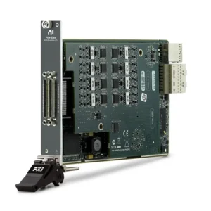


NI PXI Data Acquisition and PXIe DAQ Modules
NI PXI Data Acquisition modules provide analog input, analog output, digital I/O and counter functions inside PXI and PXI Express measurement systems. They are used to acquire electrical signals, monitor sensors, generate control voltages, read digital states and coordinate automated measurements.
Selecting the correct PXI DAQ module requires more than comparing channel count and sample rate. Engineers must consider signal range, resolution, accuracy, sampling architecture, isolation, analog output, triggering, synchronization, terminal accessories, chassis bandwidth and NI-DAQmx compatibility.
What Is PXI Data Acquisition?
PXI data acquisition combines modular DAQ hardware with a PXI chassis, system controller and measurement software. The DAQ module converts real-world analog or digital signals into data that can be processed, displayed, stored or used to control a device under test.
A PXI DAQ system can combine several measurement functions in one platform:
Analog voltage acquisition
Programmable analog output
Static or hardware-timed digital I/O
Frequency, period, pulse and event measurement
Encoder and position measurement
Hardware triggering and clock routing
Synchronization with switching, RF, digitizer and power instruments
PXI DAQ modules operate inside a compatible PXI chassis and are controlled by an embedded PXI controller or remote computer connection.
A general-purpose DAQ module measures compatible electrical signals but does not automatically provide conditioning for every sensor. Thermocouples, bridge sensors, IEPE transducers and other specialized sensors may require dedicated conditioning hardware.
PXI DAQ Measurement Architectures
DAQ Architecture
Main Characteristics
Best Fit
Primary Selection Risk
Multiplexed Analog Input
Multiple channels share analog conversion resources
General-purpose measurement and high channel density
Maximum aggregate rate may be divided across active channels
Simultaneous Sampling
Multiple analog channels are acquired at the same instant
Phase, power, transient and time-correlated measurements
Usually requires greater data throughput and more signal connections
Multifunction I/O
Combines analog input, analog output, digital I/O and counters
Automated functional test and mixed-signal validation
Not every model provides the same quantity of each I/O function
Isolated DAQ
Provides electrical separation for supported signal paths
Industrial systems, power electronics and noisy installations
Isolation topology and common-mode limits vary by module
High-Resolution DAQ
Optimized for small-signal measurement and precision
Laboratory measurement and detailed electrical characterization
Resolution alone does not define total measurement accuracy
High-Density DAQ
Provides many channels in one PXIe slot
Large automated systems with limited chassis space
Connector, cable, scan rate and aggregate throughput requirements
NI PXI Data Acquisition Model Classification
Model
Unique Category
Core Architecture
Best Fit
PXI-6115
Legacy High-Speed S Series DAQ
Traditional PXI multifunction hardware with simultaneous analog acquisition
Maintaining high-speed legacy measurement and transient-test systems
PXI-6133
Legacy Multichannel S Series DAQ
Eight-channel simultaneous analog acquisition with multifunction resources
Time-correlated legacy measurements requiring more input channels
PXI-6232
Isolated M Series DAQ
Traditional PXI multifunction acquisition with isolated signal architecture
Industrial measurement and applications involving ground-potential differences
PXI-6280
High-Resolution M Series DAQ
Precision traditional PXI analog acquisition architecture
Low-level voltage measurement and precision laboratory acquisition
PXIe-6343
General-Purpose X Series DAQ
PXIe multifunction I/O with analog input, analog output, digital I/O and counters
Balanced automated test and mixed-signal measurement systems
PXIe-6355
High-Channel-Count X Series DAQ
Multiplexed multifunction acquisition with increased analog input density
Large channel-count systems requiring versatile I/O functions
PXIe-6361
Compact High-Speed X Series DAQ
Lower-channel-count multifunction PXIe architecture with fast analog acquisition
Automated test requiring high acquisition speed without maximum channel density
PXIe-6363
Expanded-I/O X Series DAQ
Multifunction PXIe acquisition with expanded analog and digital resources
Mixed-signal test systems requiring additional I/O flexibility
PXIe-6365
High-Density High-Speed X Series DAQ
Multiplexed PXIe multifunction architecture with high analog input density
Large automated test systems combining channel density and acquisition speed
PXIe-6366
Eight-Channel Simultaneous X Series DAQ
Multifunction PXIe device with independent simultaneous analog input conversion
Phase-sensitive and time-correlated measurements with moderate channel count
PXIe-6368
Sixteen-Channel Simultaneous X Series DAQ
Higher-channel-count simultaneous acquisition with multifunction I/O
Power, transient and synchronized multichannel measurement
PXIe-6375
Maximum-Density Multiplexed X Series DAQ
208-channel multifunction analog input architecture for PXIe
High-channel-count automated test with limited chassis space
PXIe-6378
High-Performance Simultaneous X Series DAQ
Simultaneous-sampling multifunction DAQ with analog and digital triggering
Demanding time-correlated measurement and automated validation
Every model currently listed in this category is assigned to one unique architecture. Models from different generations should not be treated as interchangeable without reviewing connectors, terminal accessories, signal performance, chassis requirements and software compatibility.
How to Select a PXI Data Acquisition Module
1. Identify the Signal Type
Start by identifying the electrical output of the device or sensor. Record whether the signal is voltage, current, resistance, frequency, pulse, digital state or another electrical parameter.
Also determine whether the signal is floating or ground referenced, its source impedance, maximum amplitude, expected frequency content and any common-mode voltage.
2. Determine the Required Channel Count
Calculate the total analog input, analog output, digital I/O and counter channels. Include reference channels, test-fixture monitoring and future expansion.
A high-density module can reduce chassis usage, but it may require multiple cables and terminal blocks. Channel density should not be selected at the expense of sampling, isolation or accuracy requirements.
3. Select the Input Range
The smallest input range that accommodates the maximum expected signal generally provides better usable resolution. Include signal offset, common-mode voltage, transient conditions and overload when selecting the range.
External attenuation or conditioning may be required when signals exceed the module’s supported electrical limits.
4. Evaluate Resolution and Accuracy
ADC resolution describes the number of digital levels used to represent the signal, but it is not the same as measurement accuracy. A complete evaluation includes gain error, offset, noise, drift, input range and calibration uncertainty.
For automated production test, compare system uncertainty with the DUT tolerance and required guard band.
5. Calculate the Required Sample Rate
Select sample rate according to the signal bandwidth and transient behavior. Slowly changing control or sensor signals require less acquisition speed than switching transients, motor waveforms or fast electronic events.
For multiplexed hardware, determine whether the published sample rate is an aggregate rate shared across channels. The per-channel rate can decrease as more channels are added to the scan.
6. Choose Simultaneous or Multiplexed Sampling
Multiplexed acquisition is suitable for general measurements where small timing differences between channels are acceptable. It normally provides higher channel density and efficient use of conversion hardware.
Simultaneous sampling is preferable when phase and timing relationships must be preserved, including:
Three-phase voltage and current measurement
Power and energy analysis
Motor and inverter testing
Structural and mechanical measurements
Multichannel transient capture
Time-correlated DUT response measurement
7. Determine Whether Isolation Is Required
Isolation can reduce ground-loop problems and allow supported measurements between signals operating at different electrical potentials. It can be important in industrial machinery, power electronics, distributed sensors and electrically noisy test environments.
Check whether isolation is provided between channels, between channel banks or only between the measurement circuitry and the PXI system.
8. Review Analog Output Requirements
Multifunction DAQ modules can generate programmable analog voltages for device stimulus, control references and test sequencing. Check output channel count, update rate, range, resolution, drive capability and regeneration mode.
Applications requiring specialized waveform generation may be better served by dedicated PXI signal generators.
9. Review Digital I/O and Counters
Confirm the number of digital lines, logic compatibility, direction control, hardware timing and output-current limits. Digital I/O integrated into a multifunction DAQ device may differ from a dedicated high-performance digital instrument.
For pulse generation, event counting, frequency measurement or encoder input, verify the available counter quantity, timebase and supported routing. Dedicated PXI counter/timer modules may be appropriate when more counter resources are required.
10. Calculate Data Throughput
A simplified payload estimate is:
Data rate = active channels × sample rate × transferred bytes per sample.
For multiplexed devices, use the configured aggregate scan rate. For simultaneous-sampling devices, calculate the combined rate of every active converter. Include multiple modules operating at the same time.
The selected PXI chassis, controller, memory and storage system must sustain the complete data path.
PXI DAQ vs PXI Digitizer
Selection Factor
PXI Data Acquisition
PXI Oscilloscope or Digitizer
Primary Function
General measurement, monitoring and control
High-speed waveform and transient acquisition
I/O Functions
Can combine analog input, analog output, digital I/O and counters
Primarily optimized for analog waveform input
Channel Architecture
Multiplexed, simultaneous or isolated depending on model
Normally simultaneous waveform channels
Analog Bandwidth
Suitable for low- to moderate-frequency signals depending on model
Designed for higher-frequency signal fidelity
Triggering
Hardware triggers and flexible DAQ timing
Advanced waveform and record triggering
Best Fit
Automated functional test, sensor monitoring and mixed I/O
Fast transients, waveform characterization and electronic signal analysis
If analog bandwidth, waveform fidelity or transient capture is the primary requirement, review PXI oscilloscopes and digitizers rather than selecting a multifunction DAQ device solely because it provides analog inputs.
Triggering and Synchronization
Hardware triggering allows acquisition to begin from an electrical event, another instrument or a chassis trigger line. This provides more predictable timing than starting each operation independently through software.
PXI DAQ synchronization may use:
Shared start triggers
Shared sample clocks
Reference clocks
PXI or PXIe backplane trigger lines
External PFI connections
Dedicated synchronization hardware
Different DAQ generations may use different reference-clock resources. When synchronizing X Series, M Series and older S Series hardware, verify the supported clock and trigger routes instead of assuming that every module can use the same timing method.
For multichassis or advanced clock-distribution requirements, review PXI synchronization modules.
Sensor Measurement and Signal Conditioning
Many sensors do not produce a signal that can be connected directly to a general-purpose DAQ input. The complete system may require amplification, excitation, filtering, bridge completion, isolation or conversion to a compatible voltage.
Signal or Sensor
Possible Requirement
Selection Guidance
Conditioned Voltage
Compatible range, grounding and filtering
Often suitable for direct connection to general-purpose DAQ
Current Signal
Shunt resistor or current-input conditioning
Verify conversion accuracy and power dissipation
Thermocouple
Cold-junction compensation and low-level measurement
Use compatible temperature-measurement hardware
RTD
Precision excitation and lead-resistance compensation
Confirm 2-, 3- or 4-wire measurement support
Strain or Bridge Sensor
Bridge completion, excitation and shunt calibration
Use dedicated bridge or strain measurement hardware
IEPE Sensor
Constant-current excitation and AC/DC coupling
Use suitable dynamic signal measurement hardware
Review PXI sensor measurement modules for temperature, bridge, LVDT and conditioned-sensor acquisition, or PXI dynamic signal analysis for sound and vibration applications.
Grounding, Cabling and Measurement Integrity
The DAQ module specification represents only part of the total measurement system. Grounding, shielding, cable type, source impedance, terminal accessories and environmental interference can materially affect the result.
Common measurement problems include:
Ground loops between the DUT and PXI system
Incorrect differential or referenced single-ended configuration
Excessive source impedance when using multiplexed inputs
Long unshielded signal cables
Power-line and electromagnetic interference
Input signals exceeding the supported range or common-mode limits
Incorrect terminal-block or cable pinout
Design the complete connection from the signal source to the module before ordering hardware.
Terminal Blocks and DAQ Accessories
Many PXI DAQ modules use high-density connectors and require separately ordered cables, terminal blocks or breakout accessories. The correct accessory depends on the module connector and required signal performance.
Confirm:
Module connector type and quantity
Compatible shielded or unshielded cable
Terminal-block connector and pinout
Maximum supported signal voltage
Whether screw terminals, mass termination or direct fixture connection is required
Cable length and environmental shielding
Strain relief and rack integration
The terminal block and cable are part of the measurement path. Ordering the correct DAQ module without its required connection accessories can prevent installation or reduce measurement performance.
NI-DAQmx and Software Compatibility
NI PXI and PXIe multifunction DAQ modules are generally configured through NI-DAQmx. The driver provides device discovery, channel configuration, timing, triggering, scaling, calibration information and programming APIs.
Common software environments include:
NI Measurement & Automation Explorer for configuration and self-test
LabVIEW for custom measurement and automation applications
TestStand for automated production-test sequencing
FlexLogger for supported data logging and channel configuration
InstrumentStudio for interactive supported-device measurements
C, C++, C# and Python applications using supported NI-DAQmx APIs
Before replacing legacy hardware, confirm the required operating system, NI-DAQmx version, application bitness, LabVIEW runtime and custom-code dependencies.
Typical PXI Data Acquisition Applications
Automated functional and production testing
Electronic-device design validation
Automotive ECU and component testing
Motor, inverter and power-electronics measurement
Aerospace and avionics system validation
Industrial equipment monitoring
Multichannel voltage and sensor acquisition
Environmental and long-duration testing
Research laboratory automation
Hardware-in-the-loop support systems
Legacy PXI DAQ Replacement
Replacing a discontinued PXI DAQ module requires checking more than analog input count. A newer PXIe device may use a different sampling architecture, connector, terminal accessory, voltage range, driver or timing system.
Compare the following before approving a replacement:
PXI or PXI Express form factor
Analog input and output channel quantities
Multiplexed or simultaneous sampling
Resolution, input range and sample rate
Isolation and common-mode specifications
Digital I/O and counter resources
Trigger and clock-routing capabilities
Connector, cable and terminal-block compatibility
NI-DAQmx, operating-system and application support
Calibration and system-requalification requirements
For validated production systems, obtaining the original model can sometimes be less expensive than modifying fixtures, rewriting software and requalifying the test station.
PXI Data Acquisition Procurement and RFQ Guide
Provide the following information for accurate DAQ selection and quotation:
Exact module model and complete part number
Required analog input, analog output and digital channel quantities
Signal type and expected voltage range
Required resolution, accuracy and sample rate
Multiplexed or simultaneous-sampling requirement
Isolation and common-mode requirements
Triggering and synchronization requirements
Existing PXI/PXIe chassis and controller models
Required cables, terminal blocks and accessories
Operating system and NI-DAQmx version
Calibration-documentation requirements
Quantity, product condition, destination and delivery date
For pre-owned modules, request device recognition, self-test and functional channel-test information. Inspect high-density connectors for bent pins, contamination and physical damage before installation.
FAQ
What is the difference between multifunction DAQ and analog-input-only hardware?
Multifunction DAQ can combine analog input, analog output, digital I/O and counter functions. Analog-input-only hardware concentrates on signal acquisition and may provide different channel density, resolution or sampling performance.
What is the difference between simultaneous and multiplexed sampling?
Multiplexed hardware measures several channels through shared conversion resources. Simultaneous-sampling hardware acquires multiple channels at the same instant, preserving relative phase and timing.
Does the published sample rate apply to every channel?
It depends on the module. A multiplexed module normally specifies an aggregate rate shared across the scan, while a simultaneous-sampling module may specify a rate for each channel. Verify the exact specification wording.
Can a general PXI DAQ module measure thermocouples or strain gauges?
Only with suitable signal conditioning. Thermocouples require cold-junction compensation, and strain gauges require bridge completion and excitation. Dedicated sensor modules are usually more appropriate.
Can a traditional PXI DAQ module be installed in a PXIe chassis?
Only when the module is hybrid-slot compatible and the chassis provides a compatible hybrid peripheral slot. Check both model numbers before installation.
Can a newer PXIe DAQ module directly replace an older PXI module?
Not automatically. Differences in chassis interface, connector, terminal block, sampling architecture, timing and software can require hardware and application changes.
Do I need a terminal block and cable?
Usually yes for modules using high-density connectors. Confirm the complete connection path from the DAQ module to the DUT or sensor before ordering.
When should I choose a PXI digitizer instead?
Choose a digitizer when higher-frequency waveform capture, analog bandwidth, transient performance or detailed waveform triggering is the primary requirement.
Recommended NI PXI Data Acquisition Modules
Consider the PXIe-6343 for balanced multifunction I/O, the PXIe-6365 for high-density high-speed acquisition, the PXIe-6368 for multichannel simultaneous sampling, or the PXIe-6375 for maximum analog input density.
Related NI Measurement Platforms
Use CompactDAQ systems for portable or distributed sensor acquisition, PCI and USB DAQ for direct computer-based measurement, or explore additional PXI modules for RF, switching, power and specialized sensor functions.
NI PXI Data Acquisition Modules from PXISOURCE
PXISOURCE supports engineers, system integrators, laboratories and procurement teams with PXI DAQ selection, chassis compatibility review, cable and terminal-block matching, current-product sourcing and legacy-module replacement. Send the signal type, channel count, sample rate, chassis model and preferred hardware condition for a technically matched quotation.