



Отображение единственного товара




Filter by brands

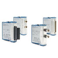
NI C Series Digital Output Modules
NI C Series Digital Output Modules generate logic-level, industrial-voltage, relay or solid-state control signals from compatible CompactDAQ and CompactRIO systems. They are used for machine control, test-fixture actuation, relay control, valve commands, interlocks, status indicators, sensor simulation and hardware-in-the-loop applications.
The correct module depends on the electrical requirements of the device being controlled. TTL, sourcing, sinking, 24 V field output, relay and solid-state output architectures have different voltage, current, isolation, switching-speed and wiring requirements.
What Is a C Series Digital Output Module?
A C Series digital output module changes an external output between defined logical states under software, hardware-timed or FPGA-based control. The module can command compatible devices such as PLC inputs, relays, indicators, solenoids, contactors, test fixtures and digital control interfaces.
Digital output modules provide control signals; they are not universal power sources. Every channel has voltage, current, thermal and switching limits that must be checked against the connected load and external power-supply arrangement.
Do not directly drive a high-power, inductive or safety-critical load from a general digital output channel unless the module and complete interface circuit are designed for that load. Use suitable external relays, drivers, fuses, suppression devices and independent safety circuitry where required.
C Series Digital Output Types
Output Type
Typical Controlled Device
Key Selection Factors
Typical Applications
TTL and Logic-Level Output
Electronic circuits, test fixtures and compatible logic inputs
Logic level, switching rate, output direction, reference and cable length
Digital test, device simulation, logic control and laboratory automation
High-Speed Digital Output
Rapid logic transitions, pulse trains and timed digital stimulus
Maximum update rate, hardware timing, buffering, synchronization and cable quality
Pulse generation, fast digital test, synchronized stimulus and FPGA control
Industrial Sourcing or Sinking Output
PLC inputs, industrial relays, valves and field-control interfaces
Output voltage, current capacity, sourcing or sinking behavior, external power and isolation
Factory automation, machine control and process equipment interfaces
Relay Output
Contact closure, low-speed switching and electrically separated control paths
Contact rating, switching frequency, load type, relay life and isolation requirements
Fixture control, low-speed actuator control, routing and on/off commands
Solid-State Relay Output
Frequent switching of compatible AC or DC loads
Load type, off-state leakage, voltage drop, thermal dissipation and switching behavior
Industrial automation, repetitive switching and electronic load-control interfaces
Representative NI C Series Digital Output Modules
Model
Unique Category
Key Differentiator
Best Fit
NI-9401
High-Speed TTL Digital I/O
Fast bidirectional logic-level interface
Digital test, pulse generation, custom timing and embedded control
NI-9472
Industrial Digital Output
Field-level digital output architecture for industrial control signals
PLC interfaces, indicators, relays and machine-control commands
NI-9474
High-Current Industrial Digital Output
Industrial output capability for compatible field loads
Industrial actuators, control panels and test-fixture output control
NI-9476
High-Density Industrial Digital Output
Higher channel density for large field-output systems
Production fixtures, machine control and multichannel status commands
NI-9481
Relay Digital Output
Relay-based switching for electrically separated control paths
Contact closure, low-speed control and fixture interface applications
NI-9485
Solid-State Relay Output
Solid-state switching architecture for compatible controlled loads
Frequent switching and industrial electronic control applications
This table represents common digital output architectures rather than every available C Series module. Confirm the exact output voltage, maximum current, load type, isolation arrangement, terminal accessory and software support before ordering.
How to Choose a C Series Digital Output Module
1. Identify the Receiving Device Input
Start with the datasheet for the device being controlled. Determine whether it accepts TTL logic, a sourcing or sinking industrial signal, relay contact closure, a solid-state switch or another digital interface.
Record the required voltage, input current, polarity, switching speed, common reference, external supply and safe-state requirement. These values determine the correct output architecture.
2. Determine Sourcing or Sinking Requirements
Industrial digital output systems can be sourcing or sinking. A sourcing output supplies positive voltage to the connected load, while a sinking output provides a path from the load to the return reference.
The module, load and field power supply must be wired as a compatible circuit. Verify the wiring diagram before connection; a sourcing output is not automatically interchangeable with a sinking output.
3. Check Channel Current and Total Module Load
Each channel has a maximum output current, and the module can also have a total current or thermal limit. The external load current must remain within both limits under all operating conditions.
Do not add the nominal current of several loads without checking startup, inrush and fault current. Solenoids, contactors, lamps and motors can draw substantially more current during switching than their normal steady-state value.
4. Select Relay or Solid-State Output When Needed
Relay outputs provide contact-based switching and can be useful when electrical separation or simple contact closure is required. However, relay contact life depends on current, voltage, load type and switching frequency.
Solid-state relay outputs can support frequent switching but have different behavior, including on-state voltage drop, off-state leakage and heat dissipation. Confirm that the receiving load is compatible with the selected solid-state output type.
5. Define the Required Switching Speed and Timing
Slow outputs such as alarms, lamps and relay commands can often be controlled through software-timed updates. Fast pulse trains, synchronized digital stimulus, encoder emulation and hardware interlocks require suitable hardware timing or FPGA logic.
For precise timing, define the required pulse width, edge placement, update rate, synchronization source and latency tolerance. A general digital output is not automatically suitable for high-speed waveform generation.
6. Plan Fault and Safe-State Behavior
Digital outputs can directly influence equipment. Define the required output state during system power-up, application startup, software failure, watchdog timeout, communication loss and emergency shutdown.
Use independent safety-rated circuits when the controlled device presents a risk to personnel, equipment or the test article. A software-controlled digital output should not be the only protective layer in a safety-critical system.
Industrial Digital Output Wiring
Industrial output modules commonly interface with PLC inputs, relays, valves, annunciators and machine-control systems. Correct wiring requires compatible field power, a defined common reference, suitable protection and appropriate cable routing.
Before wiring an industrial digital output, confirm:
Required output voltage and load current
Sourcing, sinking or push-pull control architecture
External field power-supply voltage and polarity
Per-channel and total module current limits
Isolation topology and grounding arrangement
Load type: resistive, inductive, capacitive or electronic input
Required suppression for inductive loads
Fuse, breaker, terminal and cable requirements
Inductive Loads and External Protection
Inductive loads such as relays, solenoids, valves, contactors and motor-control coils can generate voltage transients when switched off. These transients can damage output circuitry or create electrical noise that affects the rest of the measurement system.
Use the appropriate external suppression method for the load and circuit, such as a flyback diode for a DC coil or a suitable snubber, transient suppressor or external driver. The protection method must be selected for the actual voltage, current and required release time.
Digital Output Timing and FPGA Control
When outputs must change in precise relation to analog measurements, digital inputs or external events, configure a shared timing architecture rather than relying on software-loop timing. Hardware clocks, triggers and timestamps can provide more repeatable behavior.
CompactRIO systems can use FPGA logic for deterministic output timing, custom pulse sequences, interlocks and fast response. Verify module support, FPGA resources and application timing before committing to the design.
CompactDAQ and CompactRIO Compatibility
C Series digital output modules can be used in compatible CompactDAQ systems and CompactRIO systems. The selected platform affects software support, synchronization, timing precision and embedded deployment options.
CompactDAQ is suitable for PC-based test fixtures, monitoring and general automation. CompactRIO is appropriate when the application requires deterministic output behavior, local real-time execution, FPGA timing or embedded control.
Software and System Integration
CompactDAQ systems commonly use NI-DAQmx for digital output configuration, timing and software control. CompactRIO systems can use NI-RIO, LabVIEW Real-Time and LabVIEW FPGA for embedded applications and custom output logic.
For mixed analog and digital systems, verify the relationship between output timing, analog acquisition, digital input events and external triggers. A reliable hardware-in-the-loop or automated test system should define how every output reaches its required state during normal operation and failure conditions.
Typical Applications
PLC, relay, lamp and annunciator control
Automated functional test fixtures
Valve, solenoid and actuator command interfaces
Hardware-in-the-loop stimulus and fault insertion
Digital sensor and switch simulation
Machine automation and process control
Battery, power-electronics and energy-system test control
Automotive and aerospace validation systems
Embedded interlocks and sequence control
Laboratory instrument and fixture automation
C Series Digital Output Module Procurement Guide
Provide the following information for accurate module selection and quotation:
Receiving device manufacturer and complete model
Required output type: TTL, sourcing, sinking, relay or solid-state relay
Required output voltage, current and switching frequency
Load type and expected startup or inrush current
Required number of output channels and future expansion needs
External field power-supply voltage and wiring arrangement
Required output timing, pulse width and synchronization method
Isolation, grounding, cable length and environmental conditions
Safe-state, watchdog and fault-response requirements
Required external relays, drivers, fuses or suppression devices
Existing CompactDAQ chassis or CompactRIO controller model
Operating system, driver and software version
New or pre-owned hardware preference
FAQ
Can a digital output module directly power a solenoid or motor?
Only if the module output and complete circuit are specifically rated for the load. In most cases, use an external driver, relay, contactor or power interface with suitable suppression and protection.
What is the difference between sourcing and sinking outputs?
A sourcing output provides positive voltage to the load, while a sinking output provides the return path. The device input, module wiring and external field supply must use compatible sourcing or sinking behavior.
When should I use a relay output instead of a transistor output?
Use a relay output when contact closure or electrical separation is required and the switching rate is appropriate. Use a transistor or solid-state output when faster or more frequent switching is required and the load is compatible with that output architecture.
Why is inductive-load suppression important?
Inductive loads can generate damaging voltage transients when switched off. External suppression protects the module output and reduces electrical noise in the rest of the system.
Can digital outputs be synchronized with analog inputs?
Yes, when the selected modules and platform support the required clocks, triggers and timing configuration. Define the timing architecture before developing applications that require correlated input and output behavior.
Can C Series digital output modules be used with CompactRIO?
Yes, when the exact module is supported by the selected CompactRIO controller or chassis. CompactRIO is useful for deterministic output timing, embedded control and custom FPGA-based logic.
Related NI C Series Solutions
Explore the complete NI C Series module range for digital input, analog, temperature and communication I/O. Pair digital output modules with a compatible CompactDAQ chassis for PC-based control, or a CompactRIO controller for embedded real-time and FPGA applications.
NI C Series Digital Output Modules from PXISOURCE
PXISOURCE supports engineers, system integrators and procurement teams with digital output module selection, load and field-power review, CompactDAQ and CompactRIO compatibility checks, wiring accessory matching and legacy-module replacement. Send the receiving-device datasheet, output voltage, load current, switching requirement, platform model and preferred hardware condition for a technically matched quotation.
Need help selecting an NI C Series digital output module? Email [email protected] or contact PXISOURCE on WhatsApp.