




Отображение 1–16 из 32




Filter by price
Filter by brands



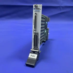
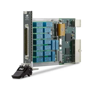

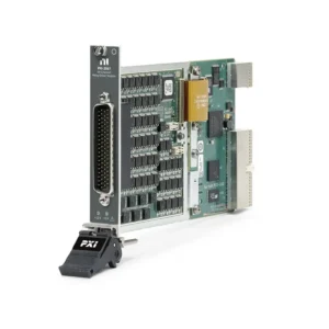
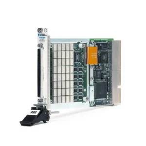


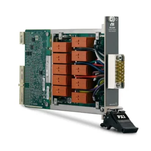

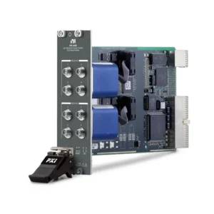
NI PXI and PXIe Switch Modules
NI PXI switches provide software-controlled signal routing between measurement instruments, stimulus sources, loads and devices under test. They allow one instrument to service many test points, connect multiple instruments to different DUT terminals and automate routing operations that would otherwise require manual rewiring.
PXI switch modules include multiplexers, matrices, independent relays, external relay drivers and RF switches. Selecting the correct module requires more than comparing channel count. Engineers must define the required topology and verify voltage, current, switching power, bandwidth, path resistance, isolation, relay life, connectors and software compatibility.
What Does a PXI Switch Do?
A PXI switch normally does not generate or measure the signal. It establishes the electrical path so another instrument can perform the required measurement or stimulus function. For example, a multiplexer can connect one digital multimeter to many test points, while a matrix can dynamically connect several instruments to multiple DUT terminals.
Because the switch becomes part of the signal path, its resistance, leakage, thermal offset, bandwidth, insertion loss and isolation can affect measurement accuracy. Switching hardware should therefore be selected together with the connected instruments, cables, terminal blocks and test fixture.
Main Types of PXI Switch Modules
Switch Type
Routing Architecture
Best Fit
Important Specifications
Multiplexer
Connects one or several common paths to many selectable channels
Scanning many DUT points with one DMM, DAQ device or source
Channel count, wire mode, voltage, current, resistance and scan rate
Matrix
Provides configurable row-to-column connections
Flexible routing between multiple instruments and DUT nodes
Rows, columns, crosspoints, simultaneous routes, resistance and isolation
Independent Relay
Provides separately controlled SPST, SPDT or other relay contacts
Power interruption, load control, fault insertion and fixture automation
Contact configuration, voltage, current, power and relay life
Relay Driver
Controls external relays rather than routing signals through onboard contacts
Custom fixtures, external relay banks, solenoids and inductive loads
Output quantity, drive voltage, drive current, protection and external supply
RF Multiplexer
Routes controlled-impedance high-frequency paths
RF instrument sharing, multi-DUT testing and antenna or port selection
Frequency range, impedance, insertion loss, isolation, VSWR and RF power
Transfer and Fault-Insertion Switch
Selects alternate paths or deliberately opens, shorts or redirects signals
ECU, avionics, communications and hardware-in-the-loop validation
Topology, fault states, simultaneous connections and electrical ratings
Multiplexer vs Matrix Switching
Selection Factor
Multiplexer
Matrix
Basic Architecture
One or several common connections routed to many channels
Multiple rows connected to multiple columns through crosspoints
Typical Use
One instrument sequentially measures many DUT points
Several instruments require flexible access to multiple DUT nodes
Routing Flexibility
Optimized for defined one-to-many paths
Supports more flexible instrument-to-DUT connection patterns
Channel Efficiency
Generally efficient for scanning applications
Depends on the required number of rows, columns and simultaneous routes
System Complexity
Relatively straightforward wiring and programming
Requires careful route planning and prevention of conflicting connections
Common Application
DMM channel expansion and multipoint data acquisition
Semiconductor characterization and multi-instrument automated test
If one DMM must sequentially measure 32 DUT points, a multiplexer is usually the more direct architecture. If several instruments must dynamically connect to many terminals, a matrix provides greater routing flexibility.
Define the complete connection map before selecting a switch. Two modules with similar channel counts may have incompatible topologies and cannot necessarily replace one another.
How to Select a PXI Switch Module
1. Define the Required Routing Topology
Begin by identifying every instrument, source, load and DUT connection. Determine which paths must be connected, which connections must exist simultaneously and whether shared returns or differential pairs are permitted.
This determines whether the system needs a multiplexer, matrix, independent relay, relay driver, RF switch or fault-insertion architecture. For a matrix, specify the number of rows, columns and crosspoints. For a multiplexer, specify the number of common paths, channels, banks and required wire mode.
2. Select the Correct Wire Mode
One-wire switching provides high channel density but normally uses a shared return. Two-wire switching routes both signal conductors and is common for differential or floating measurements. Four-wire switching routes separate source and sense connections for precision resistance measurement.
Changing wire mode normally changes the available channel count. Confirm the required measurement method before comparing module channel specifications.
3. Confirm Voltage, Current and Switching Power
Maximum voltage and maximum current ratings should not be treated as simultaneously available under every condition. Relays also have switching-power limits that depend on the signal type and load.
Check both normal operating levels and possible transient or fault conditions. Battery systems, power supplies, motors, solenoids, capacitive loads and inductive loads can place additional stress on relay contacts.
4. Distinguish Switching and Carry Ratings
A relay may be able to carry a certain current after closing but may not be able to safely make or break that same current. Switching ratings describe the energized conditions under which the contacts can change state, while carry ratings describe the current that can flow through an established path.
Review voltage, current and power ratings for the exact AC, DC or RF signal being routed.
5. Determine Hot or Cold Switching
Cold switching changes relay state while little or no voltage and current are present across the contacts. Hot switching opens or closes an energized circuit and generally places more electrical stress on the relay.
When possible, disable the source or load before changing relay state. This can reduce contact wear and extend electrical relay life. The applicable switching sequence should be included in the test-system design rather than left entirely to operator practice.
6. Review Low-Level Measurement Performance
For precision resistance, low-current, low-voltage or semiconductor measurements, consider path resistance, resistance stability, leakage current, thermal EMF and insulation resistance. These characteristics can contribute directly to measurement uncertainty.
Very low resistance measurements may require four-wire routing. Sensitive current measurements may require low-leakage switching, guarded connections and careful fixture insulation. A high-voltage switch is not automatically suitable for low-level precision measurement.
7. Match Bandwidth to the Routed Signal
A switch must pass the frequency content of the signal without unacceptable attenuation or distortion. Fast digital edges and transient waveforms can require substantially more bandwidth than their repetition rate suggests.
For RF paths, verify characteristic impedance, insertion loss, isolation, return loss or VSWR, connector type and RF power handling. Include cables, adapters and fixtures when calculating the complete RF path budget.
8. Evaluate Relay Technology and Lifetime
Electromechanical and reed relays provide galvanic isolation but are mechanical wear components. Solid-state switching can provide faster operation and very long cycle life, but its leakage, on-resistance and signal behavior differ from mechanical contacts.
Estimate the expected relay operations from DUT volume, number of tests per unit and planned equipment life. Electrical relay life can be much shorter than mechanical life when contacts switch energized loads.
9. Calculate Switching and Measurement Throughput
Total test time includes relay actuation, relay settling, signal-path settling, instrument configuration, measurement integration and software overhead. A faster relay does not necessarily improve throughput when the connected instrument or DUT requires a longer settling period.
Supported hardware triggering can coordinate the switch with a DMM or other instrument and reduce the timing variation associated with software-controlled scanning.
10. Confirm Connectors, Cables and Terminal Blocks
Many PXI switches require dedicated terminal blocks, connector blocks or cable assemblies. Some terminal blocks also determine the available topology. Verify the complete signal path from the module to the instrument and DUT before ordering.
Check connector type, pinout, wire gauge, insulation, shielding, cable length and electrical ratings. For RF switching, confirm impedance and every connector transition.
Representative NI PXI Switch Modules
Model
Unique Category
Key Differentiator
Best Fit
PXI-2527
High-Voltage Multiplexer
Configurable 64×1 one-wire, 32×1 two-wire or 16×1 four-wire topology with ratings up to 300 V and 2 A
DMM channel expansion, high-voltage scanning and two- or four-wire measurements
PXI-2529
Configurable Low-Offset Matrix
128-crosspoint, two-wire matrix configurable as 4×32 or 8×16 through the selected terminal block
Precision low-level routing, functional test and flexible instrument-to-DUT connections
PXI-2532B
High-Density Reed Matrix
512 reed-relay crosspoints with configurable matrix dimensions and up to 30 MHz switch bandwidth
High-density automated signal routing and semiconductor test systems
PXI-2567
External Relay Driver
64 control channels for driving external relays, relay coils, small DC motors and compatible inductive loads
Custom test fixtures and externally located high-power relay assemblies
PXI-2575
High-Density Scanning Multiplexer
Up to 196×1 one-wire or 98×1 two-wire routing with 100 V and 1 A switching capability
Large channel-count scanning and production data acquisition
PXI-2586
High-Current Power Relay
Ten independent SPST Form A relay channels rated up to 12 A and 300 V
Battery, power-supply, automotive load and control applications
PXI-2593
Sub-GHz RF Multiplexer
Sixteen-channel, 50 Ω RF switching from DC to 500 MHz with configurable 16×1 or dual 8×1 operation
Communications, video, RF production and shared-instrument routing
PXIe-2738
Health-Monitored PXIe Matrix
Fixed 8×32 two-wire matrix with 256 crosspoints, fast scanning and supported relay-health diagnostics
Long-life production systems requiring dense matrix routing and preventive maintenance
PXIe-2747
2.7 GHz RF Multiplexer
Two independent 8×1, 50 Ω RF multiplexer banks operating up to 2.7 GHz
Multi-DUT RF test, analyzer sharing and automated wireless-device validation
This table represents major switch architectures rather than every NI legacy or specialized model. Verify the complete part number, topology, electrical limits, accessory requirements and driver support before approving a module.
Integrating PXI Switches with Measurement Instruments
Digital Multimeter Scanning
A multiplexer can expand one PXI digital multimeter across many DUT channels. The test sequence connects a channel, allows the path to settle, performs the measurement and then advances to the next channel.
For resistance measurement, confirm whether two-wire or four-wire switching is required. Relay and lead resistance become part of a two-wire measurement.
DAQ Channel Expansion
Switch modules can route multiple low-rate signals into compatible PXI data acquisition modules. Confirm that the relay scan rate, signal settling and DAQ acquisition sequence support the required overall channel-update rate.
SMU and Semiconductor Test
Matrix switching can connect several PXI power supplies and SMUs to multiple device terminals. Sensitive semiconductor measurements may require special attention to leakage, thermal EMF, guarding, settling and safe discharge before routes change.
RF Signal Routing
RF switches are often paired with PXI RF and wireless instruments. The complete path—including the switch, coaxial cables, adapters and fixture—must meet the required frequency, impedance, insertion-loss, isolation and power specifications.
Hot Switching, Cold Switching and Relay Protection
Operating Method
Relay Condition
Primary Consideration
Cold Switching
Relay changes state with little or no voltage or current across the contacts
Generally reduces electrical contact wear when supported by the test sequence
Hot Switching
Relay makes or breaks an energized circuit
Must remain within switching voltage, current and power ratings
Carry Only
Relay closes before the load is applied and opens after the load is removed
Carry ratings still cannot exceed the module, accessory or cable limits
Inductive Switching
Relay controls a motor, solenoid, transformer or relay coil
May require suitable transient suppression to control flyback voltage
Capacitive Switching
Relay connects a discharged capacitor or capacitive load
Inrush current may exceed the normal steady-state current
Never assume that a relay’s maximum voltage and maximum current can be switched together. Use the module specifications and load characteristics to determine the allowable operating point.
Relay Life and Preventive Maintenance
Relay-based switch modules are wear components in high-cycle automated systems. Actual service life depends on relay technology, switched voltage, current, power, signal type, switching frequency and environmental conditions.
Estimate expected relay operations using:
Expected relay operations = DUT quantity × tests per DUT × relay operations per test.
Onboard relay-count tracking and supported health-monitoring tools can help plan maintenance. Relay counts indicate usage but do not replace electrical verification of critical signal paths. Production systems may require resistance checks, self-tests or fixture-level validation at defined intervals.
Software Control and Switch Management
NI PXI switches are commonly controlled with the NI-SWITCH instrument driver. Applications can select a topology, connect and disconnect channels, configure scan lists, use hardware triggers and read supported relay-count information.
NI Switch Executive provides graphical route configuration, channel aliases, route groups and virtual-device management for larger switching systems. It can simplify application maintenance when several modules operate as one logical routing network.
Switching can be integrated into LabVIEW, TestStand and compatible programming environments. Verify the supported operating system, NI-SWITCH version, Switch Executive version and application API before replacing legacy hardware.
PXI and PXIe Compatibility
Conventional PXI switch modules use a PCI-based backplane connection, while PXI Express switch modules use the PXIe architecture. Some traditional PXI modules use hybrid-compatible connectors and can be installed in suitable PXIe hybrid slots.
A physical fit does not guarantee complete compatibility. Check:
PXI, PXIe or hybrid module connector
Selected chassis slot type
Module power and cooling requirements
Front-panel space for cables and terminal blocks
Operating-system and driver support
Required triggers and synchronization routes
Review the selected PXI or PXIe chassis slot map before ordering modules for a mixed-generation system.
Switch Cables and Terminal Accessories
The switch module and its connectivity should be treated as one assembly. Depending on the model, the system may require a direct-mount terminal block, DIN cable, D-SUB breakout, bare-wire cable, MCX coaxial cable, RF adapter or custom fixture interface.
Switch Family
Connectivity to Confirm
Common Procurement Risk
High-Voltage Multiplexer
Terminal-block voltage rating, insulation, wire mode and conductor size
Accessory rating is lower than the module rating
Matrix Switch
Terminal block or cable that supports the required row and column configuration
Wrong accessory creates an unsuitable topology
High-Current Relay
Wire gauge, connector current rating, load protection and strain relief
Connector or cable cannot carry the required current
Relay Driver
External supply, coil voltage, drive current and flyback protection
Treating a driver module as an integrated signal switch
RF Switch
Impedance, connector type, cable loss, adapters and calibration plane
RF performance is degraded by unsuitable cables or transitions
Typical PXI Switch Applications
Automated electronic functional testing
Digital multimeter channel expansion
Semiconductor characterization and production test
PCB, component and subsystem validation
Battery and power-management testing
Automotive ECU and hardware-in-the-loop validation
Sensor simulation and fault insertion
Avionics and aerospace subsystem testing
RF signal routing and multi-DUT wireless testing
Communications and radar-system validation
Production fixture control and load switching
Laboratory instrument automation
Legacy PXI Switch Replacement
Replacing a legacy PXI switch requires more than matching the number of channels. Even similar models can use different topologies, relay technologies, connectors, terminal blocks and channel names.
Compare the following before approving a replacement:
PXI, PXIe and hybrid-slot compatibility
Multiplexer, matrix or relay topology
One-wire, two-wire or four-wire operation
Channel, bank, row and column configuration
Voltage, current, switching-power and carry ratings
Path resistance, leakage and thermal EMF
Bandwidth, isolation and RF impedance
Connector, cable, terminal-block and fixture pinout
Relay behavior and switching sequence
NI-SWITCH, operating-system and software compatibility
A newer module may provide better performance but still require fixture rewiring, software modifications and system requalification. For validated production equipment, retaining the same model may sometimes reduce migration risk.
PXI Switch Procurement and RFQ Guide
Provide the following information for accurate module selection and quotation:
Exact model and part number when known
Required switch topology
Channel count, matrix dimensions or relay quantity
Number of simultaneous connections
One-wire, two-wire or four-wire requirement
Maximum signal voltage and current
Maximum switching power and load type
Hot- or cold-switching requirement
Signal bandwidth or RF frequency range
Impedance and connector requirements for RF signals
Low-level measurement requirements
Existing PXI or PXIe chassis model
Required terminal blocks, cables and accessories
Operating system and NI-SWITCH version
Required product condition, quantity and destination
If the model has not been selected, provide a routing diagram showing the instruments, DUT connections and paths that must operate simultaneously. This is often the most effective way to identify the correct topology.
FAQ
What is the difference between a PXI multiplexer and a matrix?
A multiplexer connects one or a small number of common paths to many selectable channels. A matrix provides configurable row-to-column connections and is better suited to routing several instruments among multiple DUT nodes.
Can one PXI switch be used with a DMM, DAQ module and SMU?
Potentially, but the switch must satisfy the electrical and measurement requirements of every connected instrument. Topology, voltage, current, resistance, leakage, thermal EMF, bandwidth and isolation may all affect suitability.
What is the difference between hot and cold switching?
Hot switching changes relay state while voltage and current are present. Cold switching changes state with little or no electrical load across the contacts. Hot switching generally creates more contact stress and must remain within the specified switching limits.
Does maximum current mean the relay can switch that current?
Not necessarily. A carry-current rating describes current through an established path, while the allowable switching current may be lower. Voltage, current, switching power and load type must be considered together.
Which PXI switch is suitable for four-wire resistance measurement?
Select a module and topology that route separate source and sense conductors. The PXI-2527, for example, supports a 16×1 four-wire multiplexer configuration. The complete path must also be evaluated for resistance, thermal EMF and fixture effects.
What should be checked when selecting an RF PXI switch?
Confirm frequency range, characteristic impedance, insertion loss, isolation, VSWR or return loss, RF power, connector type and routing topology. Include cables and fixtures in the complete path calculation.
Do PXI switches require terminal blocks or cables?
Frequently yes. Many modules require a dedicated terminal block, breakout cable or RF interconnect. The selected accessory may also determine the available switch topology.
Can a conventional PXI switch be installed in a PXIe chassis?
Only when the chassis provides a compatible hybrid slot and the switch uses a suitable connector. Check the exact chassis slot map and module documentation before installation.
Related NI PXI Solutions
Explore additional NI PXI modules when the system also requires acquisition, digitization, signal generation, programmable power, RF measurement, FPGA processing or industrial communication. Select the switch and measurement instruments as one coordinated signal chain.
NI PXI Switch Modules from PXISOURCE
PXISOURCE supports engineers, system integrators, laboratories and procurement teams with PXI switch topology review, model identification, chassis compatibility, terminal-block matching, RF connectivity and legacy switch replacement. Send the required routing diagram, electrical limits, chassis model and preferred product condition for a technically matched quotation.
Need help selecting the right NI PXI switch? Email [email protected] or contact PXISOURCE on WhatsApp.