




Showing all 5 results




Filter by price
Filter by brands

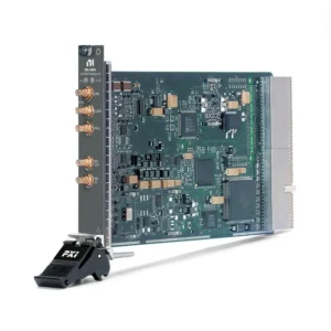

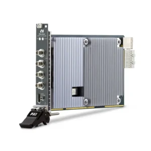

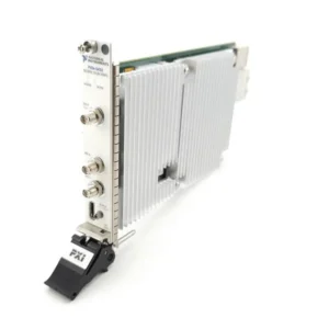
NI PXI Signal Generators and Arbitrary Waveform Generators
NI PXI Signal Generators provide programmable analog stimulus for automated electronic test systems. Depending on the model, these instruments can generate clocks, sine waves, square waves, ramps, pulses and user-defined arbitrary waveforms representing complex signals, transients, recorded events or sensor outputs.
PXI waveform generators integrate with digitizers, oscilloscopes, data acquisition modules, switches and synchronization hardware inside one software-controlled system. Common applications include electronic validation, semiconductor test, sensor simulation, audio and baseband testing, component characterization, research and automated production testing.
What Is a PXI Signal Generator?
A PXI signal generator converts digitally defined waveform data into a controlled analog output. The generated signal stimulates a device under test, while another instrument measures the DUT response.
A typical automated stimulus-response path is:
PXI Signal Generator → Device Under Test → PXI Measurement Instrument
Test software can change waveform shape, frequency, amplitude, offset, phase and sequence without manual instrument adjustment. Hardware triggers and PXI timing resources allow the generated stimulus to be coordinated with acquisition, switching and other test operations.
Main Types of PXI Signal Generators
Generator Type
Primary Capability
Typical Signals
Best Fit
Clock and Function Generator
Direct digital synthesis of repetitive standard waveforms
Clock, sine, square, triangle and ramp
Frequency stimulus, clock testing and repetitive functional test
Arbitrary Waveform Generator
Reconstructs user-defined waveform records
Custom analog signals, transients, sensor outputs and recorded events
Device validation, sensor simulation and complex stimulus generation
Streaming AWG
Transfers long or changing waveform data during generation
Extended records, evolving patterns and test sequences
Long-duration playback and waveform sets exceeding onboard memory
Digitally Upconverted AWG
Applies onboard interpolation, I/Q processing and frequency translation
Baseband, IF and modulated waveforms
Communications, receiver and converter testing
PXI waveform generators are primarily baseband, intermediate-frequency and general electronic stimulus instruments. Applications requiring calibrated RF output power, microwave frequency coverage or standards-based wireless modulation should also review PXI RF signal generators and vector signal transceivers.
Representative NI PXI Signal Generator Models
Model
Unique Category
Core Architecture
Best Fit
PXI-5404
High-Frequency DDS and Clock Generator
Single-channel, 12-bit PXI hybrid waveform generator with up to 105 MHz bandwidth, 300 MS/s operation and a ±1 V output range
Clock, sine-wave and high-frequency repetitive waveform generation
PXI-5441
Digital-Upconversion PXI AWG
Single-channel, 16-bit, 43 MHz AWG with 100 MS/s update rate, digital upconversion, onboard processing and multiple memory configurations
Legacy baseband, IF, communications and modulated-signal systems
PXIe-5413
General-Purpose 20 MHz PXIe AWG
One- or two-channel, 16-bit AWG with 20 MHz bandwidth, fractional resampling, 128 MB memory per channel and output up to ±12 V into high impedance
Sensor simulation, electronic validation and general automated stimulus
PXIe-5423
Streaming 40 MHz PXIe AWG
One- or two-channel, 16-bit AWG with 40 MHz bandwidth, waveform scripting, streaming and 128 MB memory per channel
Complex sequences, longer waveform records and mid-bandwidth testing
PXIe-5433
High-Bandwidth 80 MHz PXIe AWG
One- or two-channel, 16-bit AWG with 80 MHz bandwidth, scripting, streaming and 512 MB memory per channel
Higher-frequency electronic stimulus, semiconductor test and demanding waveform playback
The model number alone does not indicate whether a generator is the best choice. Compare bandwidth, arbitrary-waveform rate, output range, memory, streaming, channel count, synchronization and software compatibility for the actual test requirement.
How to Select a PXI Signal Generator
1. Define the Required Waveform Type
Determine whether the DUT needs standard repetitive functions or a user-defined waveform. A clock or function generator may be sufficient for sine, square and clock stimulus. An AWG is required when the application must reproduce a custom transient, recorded signal, sensor profile, distortion pattern or fault condition.
Also identify whether several waveforms must be played in a controlled sequence. Waveform scripting can select, repeat and branch between stored records without transferring every sample again from the controller.
2. Select the Required Analog Bandwidth
Analog bandwidth describes the frequency range over which the output path maintains its specified response. Select enough bandwidth for the highest waveform component that must reach the DUT accurately.
A square wave or fast pulse contains harmonics above its repetition frequency. A generator that produces the correct fundamental frequency may still round the edges if its analog bandwidth is insufficient.
3. Distinguish Bandwidth from Update Rate
Update rate describes how quickly the DAC produces waveform samples. Analog bandwidth describes the usable frequency response of the output path. These specifications are related but cannot be treated as equivalent.
Oversampling and fractional resampling can improve waveform placement and reconstruction, but a high internal DAC rate does not guarantee that every generated frequency passes through the analog output without attenuation or distortion.
4. Choose DAC Resolution for the Signal Requirement
DAC resolution defines the number of digital amplitude levels available to represent the waveform. Higher resolution can improve small-signal representation and amplitude granularity, but it does not independently determine output accuracy or signal purity.
Evaluate resolution together with noise, distortion, gain accuracy, offset accuracy, output range and the sensitivity of the DUT.
5. Calculate the Required Output Voltage
Record the minimum and maximum required amplitude, DC offset and transient peaks. Confirm whether the published range applies to a high-impedance load or a terminated 50 Ω load.
The PXIe-5413, PXIe-5423 and PXIe-5433 can provide up to ±12 V into high impedance. The achievable voltage into 50 Ω is lower because the source and load form a terminated signal path.
6. Verify Output Impedance and Load
Many waveform generators are designed for a 50 Ω signal environment. Connecting a high-impedance DUT without using the correct software or amplitude setting can produce a different voltage from the expected terminated value.
Confirm:
Generator output impedance
DUT input impedance
Cable impedance
Required termination
Maximum output current
Capacitive or reactive load behavior
A waveform generator is not a programmable power supply or power amplifier. External amplification may be required to drive speakers, actuators, transformers or other high-power loads.
7. Select One or Two Output Channels
Two-channel models can generate independent waveforms for differential stimulus, I/Q baseband signals, dual-sensor simulation and multi-input DUT testing. Verify whether both channels must operate at different rates or from independent generation engines.
For systems requiring more than two channels, determine whether several modules can be synchronized with the required phase and trigger accuracy.
8. Calculate Waveform Memory
Waveform memory limits how many samples can be stored locally. Approximate record duration can be calculated as:
Waveform duration = stored samples ÷ programmed waveform rate.
Memory requirements increase with sample width, channel count, waveform rate and the number of stored records. Account for sequence tables, alignment restrictions and reserved memory where applicable.
9. Determine Whether Streaming Is Required
Onboard generation is appropriate when the complete waveform or sequence fits in module memory. Streaming is useful when the record is larger than onboard memory or must change continuously while generation is running.
Sustained streaming depends on the complete path, including the controller, host memory, PXIe slot, chassis segment, driver buffer and application architecture. A module’s waveform bandwidth does not define its sustainable stream-from-host rate.
10. Review Scripting and Sequencing
Waveform scripting allows stored records to be repeated, linked and selected in a predefined order. It can reduce software latency because the module performs the sequence locally after the waveform data has been downloaded.
Check whether the application requires loops, triggers, conditional transitions, marker events or rapid switching between waveform segments.
11. Define Triggering and Synchronization
Signal generators may need to start from an external event, align with a digitizer or operate phase-coherently with other output modules. Determine which reference clocks, start triggers, marker events and PXI backplane routes are required.
Sharing a reference clock controls frequency drift but may not guarantee identical waveform phase. Repeatable phase alignment can also require synchronized start triggers and device-specific configuration.
12. Confirm Chassis Compatibility
The PXI-5404 and PXI-5441 use PXI hybrid-compatible connections, while the PXIe-5413, PXIe-5423 and PXIe-5433 require PXI Express-compatible slots.
Review the exact slot map of the selected PXI chassis. Physical installation, bus compatibility, cooling and synchronization resources must all be confirmed.
Function Generator vs Arbitrary Waveform Generator
Selection Factor
Function or Clock Generator
Arbitrary Waveform Generator
Waveform Creation
Defined by frequency, amplitude, offset and standard function
Defined by a user-supplied sample record
Typical Waveforms
Sine, square, clock, triangle and ramp
Custom, recorded, modulated, transient and fault waveforms
Memory Requirement
Usually limited because the function is generated mathematically
Depends on waveform length, sample width and stored sequences
Configuration
Relatively simple parameter-based setup
Requires waveform creation, download and record management
Best Fit
Repeatable standard stimulus and clock testing
Application-specific stimulus and real-world signal simulation
PXI Signal Generator vs Analog Output DAQ
Requirement
Analog Output DAQ
PXI Waveform Generator
Static Control Voltage
Often suitable
Usually unnecessary
Slow Multichannel Output
Often provides better channel density
May provide fewer channels
High-Fidelity Arbitrary Waveform
Architecture dependent
Primary design function
Advanced Sequencing
Limited or model dependent
Available on suitable AWGs
Waveform Memory
DAQ architecture dependent
Dedicated onboard waveform storage
Signal Purity and Timing
General-purpose performance
Optimized for waveform generation
If the application only requires static or slowly changing control voltages, a PXI data acquisition module may be sufficient. Use a dedicated AWG when waveform fidelity, bandwidth, sequencing, memory or synchronization is central to the test.
Output Signal Integrity
Waveform quality depends on more than bandwidth and resolution. Important specifications may include:
Total harmonic distortion
Spurious-free dynamic range
Output noise
Frequency accuracy
Clock jitter
Amplitude and offset accuracy
Channel-to-channel skew
Rise and fall time
Settling time
Flatness across the required bandwidth
The signal source should provide better performance than the DUT requirement when the test must distinguish DUT distortion, noise or nonlinear behavior from imperfections in the generated stimulus.
Reconstruction Filtering and Waveform Images
A DAC output contains the desired waveform and frequency images related to the update process. Reconstruction filters attenuate unwanted high-frequency content and smooth the generated analog waveform.
Filter selection can affect bandwidth, amplitude flatness, transient response and waveform delay. Verify whether the application prioritizes spectral purity, fast pulse edges or accurate time-domain reproduction.
Waveform Generation and PXI Switching
A suitable PXI switch can route one signal generator to several DUT points or multiple test fixtures. This can reduce the number of generator channels required in an automated production system.
The switch becomes part of the analog signal path and must support the waveform voltage, current, bandwidth, impedance and required signal fidelity. A relay module intended for DC routing may not preserve fast edges or higher-frequency waveforms.
Synchronizing Generation and Acquisition
Stimulus-response applications frequently require the signal generator and measurement instrument to share a reference clock and coordinated triggers. This allows the DUT response to be captured at a repeatable position relative to the generated waveform.
Pair the generator with PXI oscilloscopes and digitizers for waveform capture. Advanced multi-instrument or multichassis systems may require dedicated PXI timing hardware and calibrated delay correction.
Software and NI-FGEN
NI PXI waveform generators use NI-FGEN for configuration and programmatic control. Compatible applications can configure:
Standard function and arbitrary-waveform modes
Amplitude, offset, frequency and phase
Waveform memory and data download
Sequencing and scripting
Start, script and marker triggers
Reference clocks and synchronization
Output enable and generation status
NI-FGEN can be used with LabVIEW, TestStand and supported text-based programming environments. InstrumentStudio can support interactive configuration of compatible PXI waveform generators.
Before purchasing hardware for an existing system, verify the operating system, NI-FGEN version, application bitness and development-environment compatibility.
Typical Applications
Electronic circuit and component validation
Semiconductor characterization and production test
ADC and mixed-signal converter testing
Sensor and transducer simulation
ECU and industrial-controller input simulation
Audio and baseband testing
Amplifier and filter characterization
Clock and frequency stimulus generation
Transient and fault-condition reproduction
Recorded-waveform playback
Automated functional testing
Research and laboratory experiments
Sensor and Transducer Simulation
An AWG can reproduce the electrical output of a sensor without requiring the physical sensor or environmental condition to be present. This allows an automated system to apply repeatable normal, boundary and fault signals to an ECU, controller or acquisition system.
Verify that the generator can reproduce the sensor’s voltage range, source impedance, bandwidth and DC behavior. Bridge sensors, current loops, thermocouples and other specialized interfaces may require external circuitry rather than a direct voltage-generator connection.
Legacy PXI Signal Generator Replacement
Replacing an older PXI waveform generator with a newer PXIe model requires more than matching bandwidth. Differences in voltage range, output impedance, waveform memory, scripting, filtering and driver behavior can change DUT stimulus and test results.
Compare the following before approving a replacement:
PXI or PXI Express slot compatibility
Function-generator or AWG capability
Output channel count
Analog bandwidth and waveform rate
DAC resolution
Output range into high impedance and 50 Ω
Output impedance and current capability
Waveform memory
Scripting and sequence behavior
Streaming support
Reconstruction-filter response
Trigger and synchronization routes
Front-panel connector and cable type
NI-FGEN and application-code compatibility
Validated production systems should be requalified after a model change. A waveform that uses the same digital sample file can produce different analog results when generated by another instrument architecture.
PXI Signal Generator Procurement and RFQ Guide
Provide the following information for accurate module selection and quotation:
Required waveform types
Standard function or arbitrary-waveform requirement
Highest required signal frequency and bandwidth
Required waveform or update rate
Minimum DAC resolution
Output amplitude, offset and load impedance
Required output channel quantity
Waveform duration and memory requirement
Scripting, sequencing or streaming requirement
Trigger and synchronization requirements
Required signal purity, noise or distortion performance
Existing PXI chassis and controller models
Connector, cable and termination requirements
Operating system and NI-FGEN version
Existing model and part number for replacement projects
Required quantity and preferred product condition
When comparing quotations, confirm the exact channel configuration and part number. Check whether coaxial cables, auxiliary I/O accessories, calibration documentation and required software licenses are included.
FAQ
What is the difference between a function generator and an AWG?
A function generator creates standard mathematical waveforms from parameters such as frequency and amplitude. An arbitrary waveform generator reconstructs a user-defined sample record and can reproduce custom, recorded or nonstandard signals.
What is the difference between PXIe-5413, PXIe-5423 and PXIe-5433?
All three are 16-bit PXI Express AWGs available with one or two channels. The PXIe-5413 provides 20 MHz bandwidth, the PXIe-5423 provides 40 MHz plus scripting and streaming, and the PXIe-5433 provides 80 MHz bandwidth with more onboard memory.
What is the PXI-5404 best suited for?
The PXI-5404 is a single-channel DDS-based clock and waveform generator for repetitive high-frequency signals. It differs from the newer high-resolution PXIe AWGs intended for flexible multichannel arbitrary-waveform generation.
Can a PXI waveform generator replace an RF signal generator?
Only when its frequency range, output power, modulation and spectral performance meet the application. Microwave, wireless and calibrated RF tests normally require dedicated RF signal-generation hardware.
Why does the measured output voltage differ from the programmed value?
The programmed amplitude may assume a specific load impedance. Connecting a high-impedance load to an output configured for 50 Ω operation can change the measured voltage. Check the generator configuration, cable and DUT termination.
Can the output drive a speaker or actuator directly?
Not necessarily. PXI waveform generators provide precision signal stimulus but are not power amplifiers. High-current or high-power loads normally require a suitable external amplifier.
Can several waveform generators be synchronized?
Yes, when the modules support compatible clocks and trigger routes. Repeatable phase alignment may require a shared reference, synchronized triggers and instrument-specific synchronization procedures.
When is waveform streaming necessary?
Streaming is useful when the waveform is longer than onboard memory or must change continuously during generation. The controller, PXIe backplane, software buffers and generation rate must sustain the required data flow.
Related NI PXI Solutions
Combine PXI signal generators with PXI oscilloscopes and digitizers for stimulus-response measurement, PXI switches for automated signal routing, or browse additional PXI modules for complete test-system integration.
NI PXI Signal Generators from PXISOURCE
PXISOURCE supports engineers, laboratories, system integrators and procurement teams with PXI waveform-generator selection, chassis compatibility review, cable matching, software verification and legacy AWG replacement. Send the required waveform, bandwidth, voltage, channel count, chassis model and preferred hardware condition for a technically matched quotation.
Need help selecting an NI PXI signal generator? Email [email protected] or contact PXISOURCE on WhatsApp.