




Showing all 16 results




Filter by price
Filter by brands



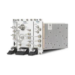


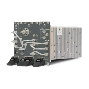


NI PXI RF and Wireless Test Modules
NI PXI RF and Wireless Test modules provide software-controlled RF signal generation, vector signal analysis, spectrum measurement, wideband transceiver operation and real-time signal processing inside PXI and PXI Express systems. They are used for RFIC characterization, wireless-device validation, semiconductor production test, radar, aerospace, defense, spectrum monitoring and communications research.
Selecting the correct RF instrument requires more than matching the carrier-frequency range. Engineers must also consider instantaneous bandwidth, RF input and output levels, dynamic range, phase noise, modulation quality, channel count, synchronization, FPGA processing, data throughput, RF path accessories and software licensing.
Main Types of PXI RF Test Instruments
Instrument Type
Primary Function
Typical Applications
Key Selection Criteria
Vector Signal Transceiver
Combines RF signal generation, RF analysis and FPGA-based processing
Wireless validation, RFIC test, radar and automated production test
Frequency range, generation and analysis bandwidth, EVM, FPGA and synchronization
Vector Signal Analyzer
Acquires RF signals while preserving amplitude and phase information
Spectrum, modulation, transmitter and signal-intelligence measurements
Frequency coverage, instantaneous bandwidth, noise floor and dynamic range
Vector Signal Generator
Generates digitally modulated RF waveforms
Receiver testing, communications validation and RF component stimulus
Modulation bandwidth, output level, EVM, phase noise and waveform memory
RF Analog Signal Generator
Produces programmable CW, swept or supported analog-modulated RF signals
Amplifier, filter, mixer and receiver characterization
Frequency range, power range, tuning speed, phase noise and spectral purity
RF Downconverter
Converts an RF signal to a lower-frequency signal for digitization and analysis
Modular VSA systems and legacy RF-analysis architectures
Frequency range, conversion bandwidth, local oscillator and compatible digitizer
RF Preamplifier
Increases low-level RF signals before analysis
Weak-signal measurement, monitoring and noise-sensitive receiver testing
Frequency range, gain, noise figure, compression and bypass operation
FlexRIO RF Digitizer
Provides high-speed conversion and FPGA-accessible signal processing
Custom radar, spectrum monitoring, communications research and streaming
Analog bandwidth, sample rate, resolution, FPGA resources and data throughput
VSA, VSG and VST Comparison
Architecture
Signal Generation
Signal Analysis
Best Fit
Vector Signal Analyzer
No
Yes
Transmitter measurements, spectrum analysis and signal monitoring
Vector Signal Generator
Yes
No
Receiver stimulus and generation of modulated RF waveforms
Separate VSA and VSG
Yes
Yes
Systems requiring independent analyzer and generator configurations
Vector Signal Transceiver
Yes
Yes
Integrated generation, analysis, FPGA processing and fast automated test
A VST can reduce the number of separate instruments in a test system, but it should not automatically replace a dedicated analyzer or generator. The decision depends on frequency coverage, measurement quality, channel requirements, existing software and whether application-specific FPGA processing is required.
Representative NI PXI RF and Wireless Test Modules
Model
Unique Category
Core Architecture
Best Fit
PXI-5652
Legacy PXI RF Signal Source
Software-controlled RF signal generation for established PXI systems
Maintenance, expansion and replacement of legacy RF test platforms
PXIe-5606
RF Downconverter
Frequency-conversion front end used as part of a compatible RF-analysis system
Modular VSA configurations requiring a separate RF front end and digitizer
PXIe-5654
Microwave Analog Signal Generator
PXIe RF source available in configurations extending to 10 GHz or 20 GHz
CW stimulus, frequency sweeps and microwave component characterization
PXIe-5668
Wideband Vector Signal Analyzer
VSA configurations covering up to 14 GHz or 26.5 GHz with wide instantaneous bandwidth
RF spectrum, modulation, radar and wideband transmitter analysis
PXIe-5698
RF Preamplifier
Single-slot broadband preamplifier designed to extend weak-signal capability
Low-level RF acquisition and expanded PXIe-5668 measurement sensitivity
PXIe-5820
Baseband Vector Signal Transceiver
Wideband differential I/Q transceiver with 1 GHz complex I/Q bandwidth and programmable FPGA resources
Baseband research, custom I/Q processing and RF front-end development
PXIe-5830
Microwave Wideband Vector Signal Transceiver
5 GHz to 12 GHz VST with 1 GHz instantaneous bandwidth and bidirectional test ports
Wideband WLAN, microwave IF and compatible mmWave test architectures
PXIe-5841
General-Purpose Wideband RF VST
Second-generation software-defined VST integrating RF generation, analysis and FPGA processing
RFIC, cellular, wireless connectivity and high-throughput production test
PXIe-5764
High-Resolution FlexRIO Digitizer
High-speed analog conversion with FPGA-accessible digital processing
Custom wideband acquisition and application-specific signal-processing systems
PXIe-5775
Ultra-High-Speed FlexRIO Digitizer
High-sample-rate acquisition combined with reconfigurable FPGA processing
Radar, transient RF capture and custom high-throughput digital signal processing
PXIe-5785
FlexRIO Transceiver Module
High-speed analog input and output with FPGA-based processing
Custom RF stimulus-response, prototyping and closed-loop signal applications
These models represent different RF architectures and should not be compared solely by model number or maximum frequency. Verify the exact part number, frequency option, bandwidth, module combination, cable kit, software license and chassis requirements before ordering.
How to Select a PXI RF and Wireless Test Module
1. Determine Whether You Need Generation, Analysis or Both
Start by defining the direction of the RF signal path. Receiver testing normally requires a controlled RF source, while transmitter testing requires an analyzer. A transceiver or complete RF component test may require both generation and analysis.
Choose between:
A dedicated RF or vector signal generator
A dedicated vector signal analyzer
Separate generator and analyzer modules
An integrated vector signal transceiver
A custom digitizer and FPGA architecture
2. Define the Required Frequency Range
The instrument must cover the DUT’s fundamental operating bands and any additional frequencies that must be generated or measured. Include harmonics, intermediate frequencies, adjacent bands, out-of-band emissions and future product variants where relevant.
Frequency range defines where the instrument can tune. It does not define how much spectrum the instrument can acquire or generate at one time.
3. Determine the Instantaneous Bandwidth
Instantaneous bandwidth is the continuous span of RF spectrum that can be generated or analyzed without retuning. It is a separate specification from the maximum carrier frequency.
Parameter
What It Defines
Why It Matters
Frequency Range
Minimum and maximum carrier frequencies
Determines which RF bands can be tested
Instantaneous Bandwidth
Spectrum captured or generated in one acquisition
Determines whether the complete modulated signal can be processed at once
Sample Rate
Digital conversion rate inside the instrument
Supports waveform and I/Q processing bandwidth
Frequency Resolution
Smallest programmable tuning increment
Affects swept measurements and precise signal placement
Wide instantaneous bandwidth is important for 5G, Wi-Fi, carrier aggregation, radar pulses, chirps, electronic warfare waveforms and wideband spectrum monitoring.
4. Specify RF Input and Output Levels
For signal generation, define the minimum and maximum output power at the DUT reference plane. For analysis, specify the expected signal range, maximum safe input and weakest signal that must be measured.
The RF path may include attenuators, amplifiers, cables, switches and fixtures. Their combined gain or loss must be included when determining the level at the instrument connector.
Never apply a signal that exceeds the analyzer’s maximum safe input. High-power amplifiers and transmitters may require external attenuation, directional couplers or other protection.
5. Review Dynamic Range and Noise Performance
Dynamic range determines how effectively the analyzer can distinguish small signals from larger nearby signals, instrument noise and distortion. Depending on the application, compare:
Displayed or average noise level
Third-order intercept performance
Spurious-free dynamic range
Harmonic and intermodulation distortion
Amplitude accuracy
Compression behavior
Available preamplification
A preamplifier such as the PXIe-5698 can improve weak-signal sensitivity, but it can also reduce the input level available before compression. Use it according to the signal environment and required dynamic range.
6. Evaluate Phase Noise and Frequency Accuracy
Phase noise affects measurements involving oscillators, synthesizers, narrowband signals, radar, communication systems and frequency conversion. Low phase noise is also important when a generator must provide a clean stimulus for receiver or component testing.
Frequency accuracy depends on the instrument timebase and external reference configuration. Systems requiring multiple coherent instruments should use a defined reference-clock architecture.
7. Define Modulation Quality Requirements
Modern communication systems require measurement of both amplitude and phase behavior. Common analysis parameters include:
Error vector magnitude
Channel power
Occupied bandwidth
Adjacent-channel power
Spectral emissions
Frequency error
Constellation behavior
Modulation accuracy
The test instrument’s residual EVM, noise and distortion should be sufficiently better than the DUT requirement. Otherwise, instrument uncertainty can consume too much of the available test margin.
8. Confirm the Required Wireless Standard
Identify the signal format and measurement standard before selecting software and hardware. Applications may include cellular, WLAN, Bluetooth, satellite communication, GNSS, proprietary radios, radar or custom digital modulation.
Hardware bandwidth alone does not provide standards-based measurements. The required RFmx measurement personality, waveform license or application software must also support the intended technology and instrument model.
9. Determine the Number of RF Channels
Single-channel systems are suitable for many component and device tests. MIMO, beamforming, phased-array and parallel-production systems may require multiple synchronized transmit and receive channels.
Define:
Number of transmit channels
Number of receive channels
Required phase relationship
Channel-to-channel skew
Local oscillator sharing
Trigger and clock distribution
Calibration method
10. Review Test Speed and Tuning Time
Production-test throughput can depend on frequency tuning, power settling, waveform loading, acquisition time, analysis time and communication with the DUT. Maximum RF performance alone does not determine total test speed.
For repeated measurements, evaluate whether the instrument and software can reuse configurations, perform list-mode operations, process measurements in parallel or use FPGA-based acceleration.
FPGA Processing in PXI RF Systems
Selected VST and FlexRIO instruments provide programmable FPGA resources close to the RF or converter hardware. FPGA processing can reduce host-data transfer, implement deterministic logic and shorten the response time between acquisition and generation.
Possible FPGA applications include:
Custom triggering
Real-time spectrum processing
Digital upconversion and downconversion
Protocol-specific processing
Pulse detection and classification
Low-latency RF control loops
Inline data reduction
Custom modulation and demodulation
FPGA capability can require LabVIEW FPGA, model-specific instrument design libraries and specialized engineering. It should be selected when the application needs customization rather than treated as a requirement for every RF test system.
Phase-Coherent, MIMO and Multichannel RF Test
Installing several RF modules in one chassis does not automatically create a phase-coherent system. MIMO, beamforming and phased-array applications require a defined synchronization and calibration architecture.
The complete design may need:
A common reference clock
Shared local oscillator signals
Matched trigger distribution
Phase-aligned acquisition and generation
Matched RF cables
Channel-to-channel phase calibration
Temperature and drift compensation
Synchronization requirements should be defined before selecting the chassis, RF instruments and cable set because they can change the complete bill of materials.
PXIe-5830 and mmWave Test Architectures
The PXIe-5830 provides two bidirectional test ports covering 5 GHz to 12 GHz with 1 GHz instantaneous bandwidth. It can serve as an IF and processing instrument within compatible microwave and mmWave test configurations.
The PXIe-5830 alone should not be assumed to provide direct access to every millimeter-wave band. A complete mmWave system may require remote frequency-conversion hardware, cables, adapters, switching, calibration accessories and model-specific configuration components.
At higher frequencies, cable loss, connector repeatability, fixture design and physical placement of frequency-conversion hardware become increasingly important.
RF Data Throughput and Streaming
Wideband instruments can generate large volumes of complex I/Q data. Approximate payload rate can be calculated as:
I/Q data rate = sample rate × bytes per complex sample × active RF channels.
A complex sample contains both in-phase and quadrature values. The transferred data representation may use more bytes than the ADC resolution alone suggests.
The complete data path includes:
RF instrument acquisition engine
Onboard memory and FPGA processing
PXIe peripheral slot
Chassis PCIe switch and segment
Controller or remote connection
System memory
Storage or network destination
RF analysis software
A module may capture a finite record at full bandwidth into onboard memory even when the complete system cannot continuously stream that data rate. Finite acquisition, real-time processing and sustained recording are different operating requirements.
PXIe Chassis and Controller Requirements
RF systems can use multiple chassis slots and require significant power, cooling and PCIe bandwidth. Some RF instruments are complete single modules, while others are systems composed of multiple modules and interconnecting cables.
Verify:
PXIe slot type and lane configuration
Number of required chassis slots
Chassis-segment bandwidth
Controller connection and memory performance
Per-slot and total cooling capacity
Required reference clocks and trigger routes
Placement of related RF modules
Front-panel cable clearance
Physical slot availability does not guarantee sufficient bandwidth, cooling or synchronization support.
RF Cables, Connectors and Signal Path
RF cables and accessories are part of the measurement system. Each component introduces insertion loss, mismatch, phase delay and frequency-dependent behavior.
A complete RF path may include:
Coaxial cables
RF adapters
Fixed or programmable attenuators
Amplifiers and preamplifiers
Directional couplers
Power splitters and combiners
Filters
RF switches
Fixture and probe interfaces
Confirm the connector series, frequency rating, loss, return loss, phase stability, power handling and cable length. Connecting incompatible connector families can damage precision RF interfaces even when they appear mechanically similar.
RF Switching and Multi-DUT Testing
RF switching allows one analyzer or generator to serve multiple DUTs or test ports. This can improve production-system utilization and reduce the number of RF instruments required.
The switch path must be evaluated for:
Operating frequency
Insertion loss
Return loss
Isolation
Power handling
Switching repeatability
Topology and port count
Switching speed and relay life
Loss and mismatch through the switch, fixture and cables should be characterized or de-embedded where required by the measurement method.
Software and RF Measurement Applications
Software
Primary Function
Compatibility to Confirm
NI-RFSA
Controls supported RF signal analyzers and acquires I/Q data
Analyzer model, operating system and driver version
NI-RFSG
Controls supported RF signal generators and generated waveforms
Generator model, waveform format and driver version
RFmx
Provides spectrum, modulation and standards-based RF measurements
Required measurement personality, license and hardware support
InstrumentStudio
Interactive instrument configuration and supported RF measurements
Instrument and software-version compatibility
LabVIEW
Automated RF applications, data processing and system integration
LabVIEW, driver and operating-system versions
LabVIEW FPGA
Custom real-time processing on supported FPGA-enabled instruments
FPGA target, instrument design library and required licenses
TestStand
Production-test sequencing, limits and result handling
Adapter, driver and application-code compatibility
RFmx measurement personalities are licensed according to the required functionality. Do not assume that purchasing an RF module automatically includes every cellular, WLAN, Bluetooth or spectrum-analysis measurement package.
Calibration, De-Embedding and Measurement Uncertainty
RF measurement results can be affected by instrument accuracy, cables, adapters, switching, fixture loss, impedance mismatch, temperature and calibration method. The reference plane should be defined before evaluating the uncertainty budget.
A complete RF accuracy plan may include:
Instrument amplitude and frequency accuracy
Generator level accuracy
Cable and adapter loss
Switch-path insertion loss
Mismatch uncertainty
Fixture characterization
Phase and group-delay error
Path-loss correction or de-embedding
Calibration interval and traceability
Self-calibration and external calibration perform different functions. System-level path correction may still be required after an instrument has received external calibration.
Typical Applications
RFIC characterization and semiconductor production test
Power amplifier and front-end module testing
Wireless transmitter and receiver validation
Cellular, WLAN and Bluetooth testing
5G and next-generation wireless research
Radar waveform generation and analysis
Electronic warfare and spectrum monitoring
Satellite and aerospace communication testing
Filter, mixer and amplifier characterization
MIMO, beamforming and phased-array validation
Automated RF production test
Custom FPGA-based RF processing
Legacy PXI RF Instrument Replacement
Replacing an older RF instrument can affect calibration, cabling, software, measurement limits and correlation with historical production data. A newer model with wider bandwidth may not be a direct substitute.
Compare the following before approving a replacement:
Generation, analysis or transceiver architecture
Minimum and maximum frequency
Instantaneous bandwidth
Input and output power ranges
Dynamic range, noise floor and phase noise
Modulation and EVM performance
RF connector type and cable configuration
Trigger, reference-clock and synchronization support
Chassis slots, bandwidth, power and cooling
NI-RFSA, NI-RFSG and RFmx compatibility
Measurement API and existing test code
Calibration procedure and test-limit correlation
Validated production systems may require software modification and measurement requalification before a newer RF instrument can replace the original hardware.
PXI RF and Wireless Test Procurement Guide
Provide the following information for model selection and quotation:
Exact NI model and part number if known
Signal generation, analysis or transceiver requirement
Minimum and maximum RF frequency
Required instantaneous bandwidth
RF input and output power ranges
Required noise floor, dynamic range or phase noise
Modulation format or wireless standard
EVM and other measurement-performance requirements
Number of transmit and receive channels
Phase-coherent, MIMO or beamforming requirements
Finite capture, real-time processing or continuous streaming
Existing PXIe chassis and controller models
Required cables, adapters, switches and frequency extensions
Operating system and NI software versions
Required RFmx measurement personalities
Calibration and traceability requirements
Required quantity, product condition and destination
For pre-owned RF hardware, request device-recognition, self-test and functional measurement results. Confirm that all required system modules, interconnecting cables and accessory kits are included where the RF instrument uses a multicomponent architecture.
FAQ
What is the difference between frequency range and instantaneous bandwidth?
Frequency range defines where the instrument can tune. Instantaneous bandwidth defines how much spectrum it can generate or analyze at one time without retuning.
What is a PXI Vector Signal Transceiver?
A VST combines vector signal generation, vector signal analysis and FPGA-based processing in a software-defined PXI instrument. It can provide stimulus and measurement functions within one integrated architecture.
Should I choose a VST or separate VSA and VSG modules?
Choose according to the required frequency coverage, bandwidth, performance, channel count, existing system and automation strategy. A VST provides integrated operation, while separate instruments may suit systems requiring independent analyzer and generator configurations.
What is the difference between the PXIe-5654 and PXIe-5841?
The PXIe-5654 is primarily an analog RF and microwave signal generator for CW and supported analog-modulation applications. The PXIe-5841 is a vector signal transceiver that integrates wideband modulated-signal generation, analysis and FPGA processing.
What is the PXIe-5668 used for?
The PXIe-5668 is a wideband vector signal analyzer for spectrum, modulation, transmitter, radar and other RF-analysis applications. Different configurations provide frequency coverage up to 14 GHz or 26.5 GHz.
Does the PXIe-5830 directly cover every mmWave frequency?
No. The PXIe-5830 provides 5 GHz to 12 GHz test ports and can operate within compatible mmWave architectures. Direct testing of higher mmWave bands can require remote frequency-conversion hardware and additional accessories.
Can multiple PXI RF instruments be phase coherent?
Yes, when the selected hardware supports the required clock, local oscillator, trigger and calibration architecture. Installing modules in one chassis alone does not guarantee phase coherence.
Can PXI RF data be streamed continuously?
It depends on I/Q sample rate, data format, channel count, FPGA processing, chassis bandwidth, controller performance and storage. Finite full-bandwidth acquisition does not automatically guarantee continuous streaming at the same rate.
Does RFmx come with every PXI RF module?
Not necessarily. RFmx measurement personalities and standards-based analysis functions may require separate licenses. Verify the exact software package and version required by the application.
Why are RF cables and adapters important?
RF interconnects introduce loss, mismatch and phase delay. Incorrect connector type, inadequate frequency rating or excessive cable loss can materially reduce measurement accuracy and may damage precision RF connectors.
Recommended PXI RF and Wireless Test Products
Consider the PXIe-5654 for analog RF and microwave stimulus, the PXIe-5668 for wideband vector signal analysis, the PXIe-5830 for 5 GHz to 12 GHz wideband transceiver applications, or the PXIe-5841 for integrated RF generation, analysis and FPGA processing.
Related NI PXI Solutions
Browse additional PXI and PXIe modules for complete automated test systems. Use PXI signal generators for non-RF waveform stimulus or review PXI oscilloscopes and digitizers for high-speed time-domain acquisition.
NI PXI RF and Wireless Test Solutions from PXISOURCE
PXISOURCE supports engineers, system integrators and procurement teams with PXI RF instrument selection, frequency and bandwidth review, chassis and controller compatibility, software verification, RF accessory matching and legacy-system replacement. Send the RF frequency range, bandwidth, signal level, modulation standard, channel quantity and existing system configuration for a technically matched quotation.
Need help selecting an NI PXI RF and wireless test solution? Email [email protected] or contact PXISOURCE on WhatsApp.